When my wife and I changed spaces in the house, I gave her my desk. That left me without a place for my computer. I decided I could make one.
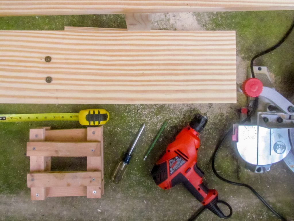
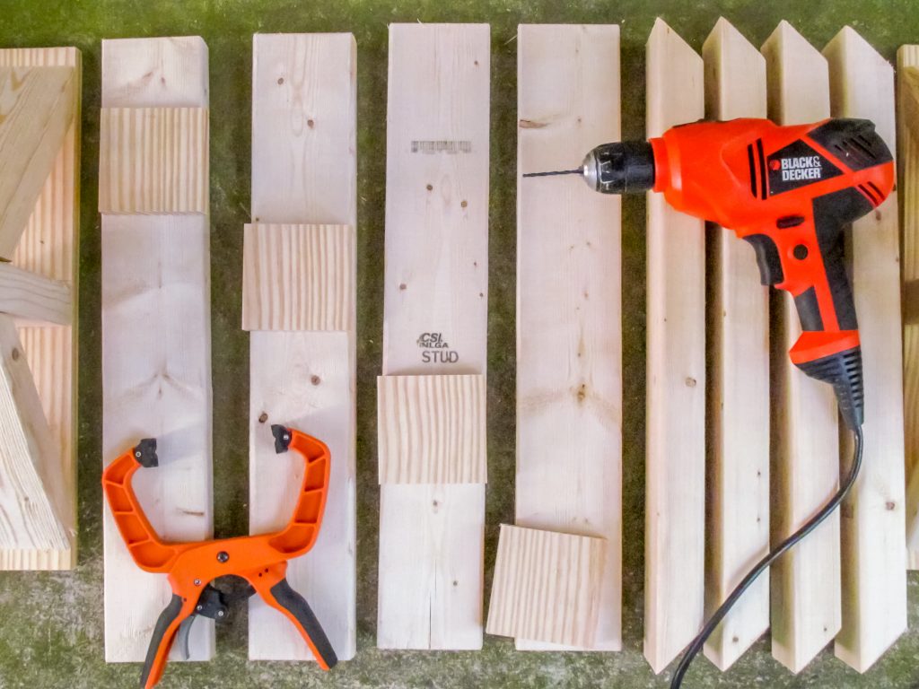
I’ve got a compound miter saw, a drill with a Kreg jig, and a tape measure. Lowes provided the lumber.
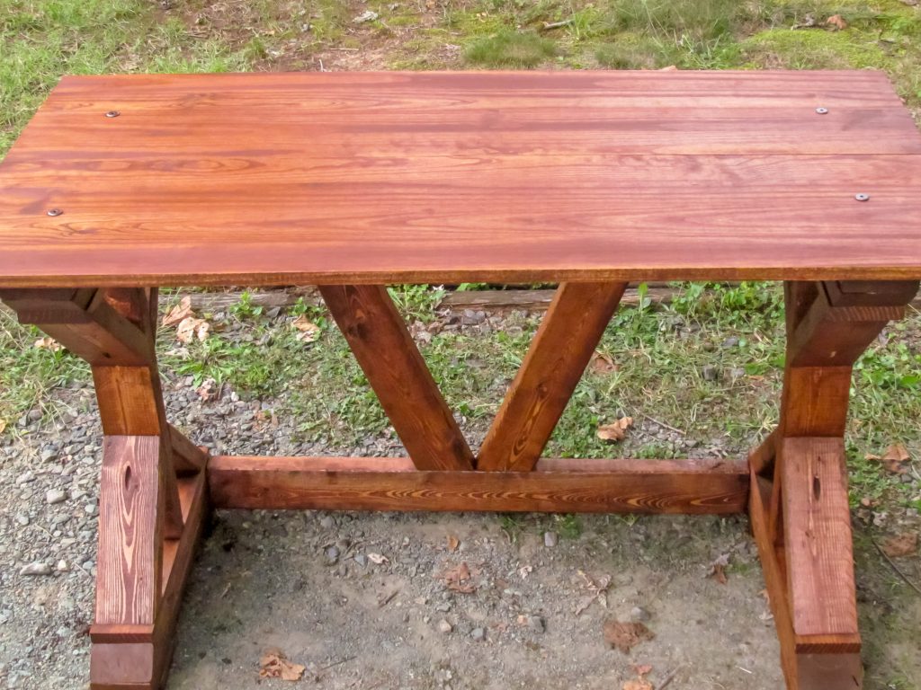
The X Desk design comes from Ana White’s website. I modified it to make the top shorter. I wanted a lighter desk that was easy to move. Except for the top, the entire desk is made from 2×4 lumber. I chose some 1×12 pine boards for the top.
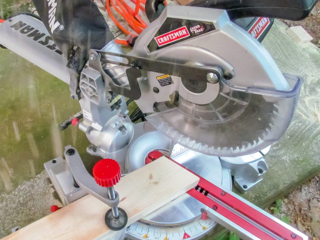
The biggest feature of the desk is the dramatic cross braces used on the single leg of the desk. Because I have a miter saw, I knew I could cut these pieces easily. I even made a modification to the design to support a narrower support. The back braces now angle 22.5 degrees.
I cut both 22.5 and 45 degree ends
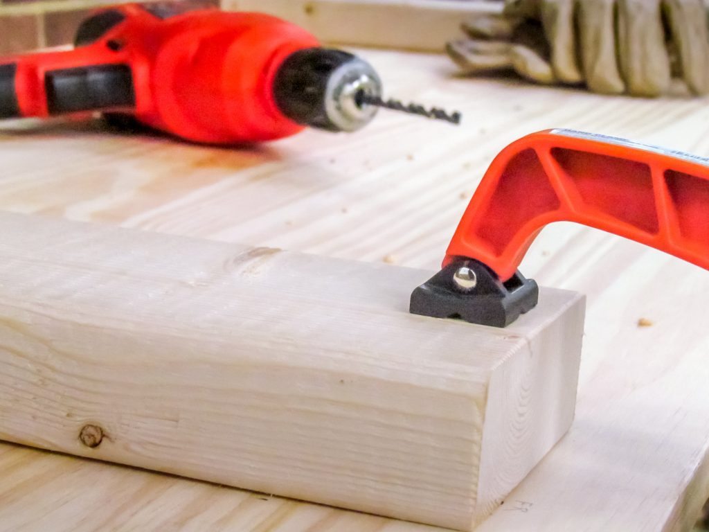
I made a decision on the top; instead of screwing in from the bottom, or countersinking screws in the top, I would use bolts. I thought flat bronze crowns for the bolts would make nice accents. Bolts would make taking the desk apart possible too.
A clamp holds the wood in place before drilling a hole
The challenge with bolts was the top layer of the legs. Two 2×4 and two more 1 inch boards meant about 4 1/2 inches to drill through and run a bolt through. I chose a trick. I embedded a T nut in the bottom side of the top leg 2×4. The nut is buried in the leg and won’t get lost. The bronze bolts run through holes in the top and holes in the leg and into the nut. Perfect.
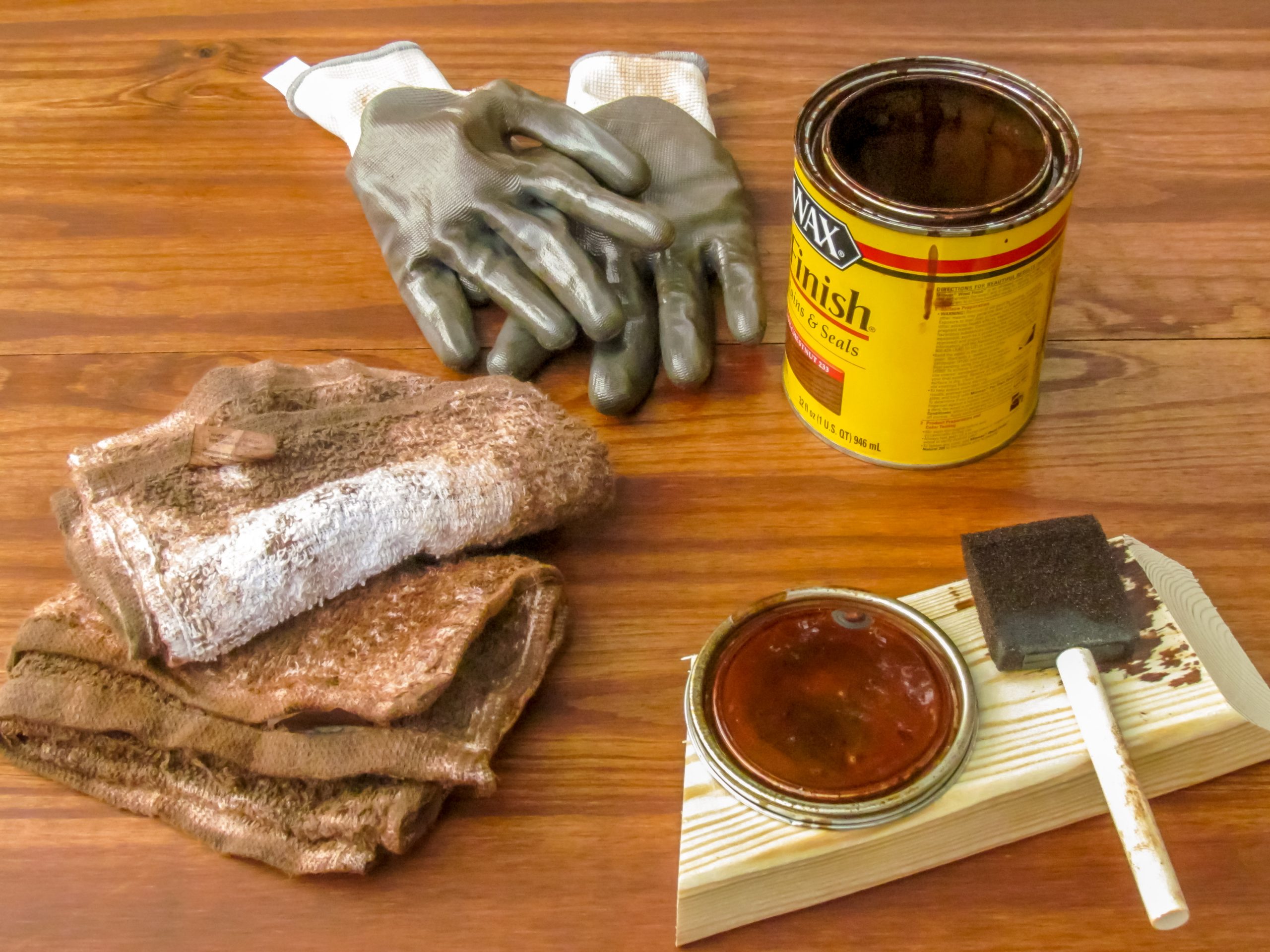
I gave the desk a light sanding before applying stain and wax. I should have bought an electric sander and given the whole thing a finer finish. About two weeks later the wax finish has just about dried. I could clear it off and give it a good polishing. I’ve been enjoying it for more than a week now.
Scientists are measuring the effectiveness of face mask materials. Most are using lab-quality expensive equipment designed to get absolute measurements and prove a very narrow hypothesis. But not all studies follow this pattern. A group of scientists and engineers from Duke University have released the results of their experiment using a low-cost method of analysis. They did it on the cheap.
The experiment uses common tools. The researchers used a laser, and cell phone, some custom software, and a guy wearing a face mask. The study follows standard practice for analysis and presentation, but the materials list seems one step above buying some materials at a hardware store. I found this intriguing. I’m going to recreate the experiment with stuff from the Dollar Tree.
My Build
I collected supplies from Dollar Tree. Three black foam boards, a plastic Fresnel lens, and a LED flashlight were the main items. I also got a laser pointer and a hand-held fan. To these I added a mobile phone from my current set.
I built the box based on several measurements. The first is the field of view of the camera used. I wanted the camera to capture as much of the spread of droplets as possible while minimizing extraneous elements like the walls. Spit floats a lot.
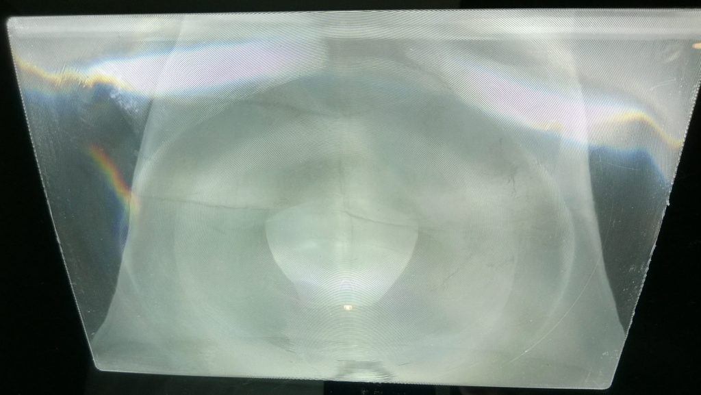
A plastic Fresnel lens
The Fresnel lens was measured next. The box needed to be wide enough to hold the entire lens, and deep enough to allow focusing of the light to occur in the center of the box. This would illuminate droplets in the narrowest horizontal and vertical slice. I wanted the spread of light from the flashlight to be the most concentrated halfway between the speaker and the camera. The Fresnel was 6.5” wide by 9.5” long and focused about 9” away. It’s strong enough to light a fire with sunlight.
The last dimension was the minimum focal distance of the camera. The box needed to be large enough that the center was within the focusing range of the camera. The minimum focal distance for the first phone I tried was 2.5”. Because the distance was so short, I felt fine making the box larger than 5” square. I didn’t need to make the box huge either.
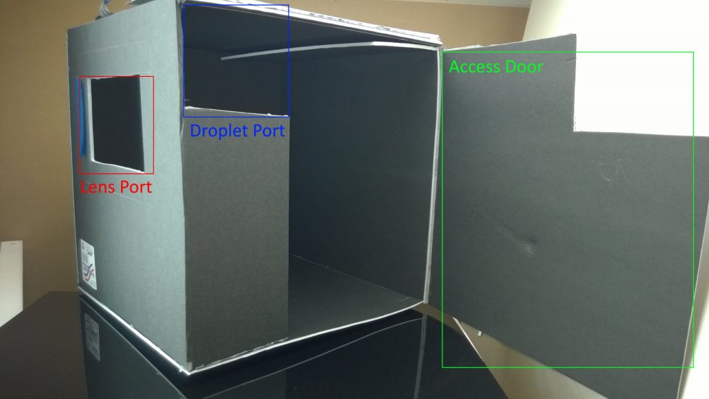
I made full use of the 20”x30” boards. The box measures 14.5” on each side. This made it easy to center the light channel, but just kept the side walls within the field of view of the camera.
Labeled box for experiment
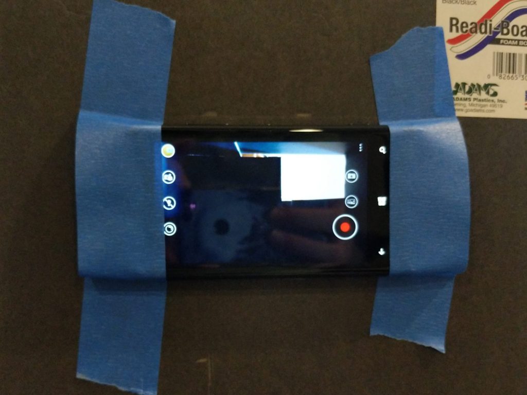
I mounted a mobile phone to the rear panel of the box. I cut a small hole and aligned the camera lens. Low tech painter’s tape sufficed to secure the phone while still allowing access to the buttons and screen. I could even see what’s in the box.
Mobile phone affixed to box
I used water in a spray bottle to test the setup. This produced a consistent heavy spray of large and small droplets. With light passing through the lens in a beam, the droplets become visible within a horizontal bar across the middle of the box.
I tried two mobile phones to record video. Each frame can be analyzed. Video should allow identifying the start of droplet production too. Because the box has depth the droplets must travel some distance to the light beam. Using the audio track I could count the travel time in frames. The first phone, a Nokia Lumia 920, was not sensitive enough to capture droplets. The second phone, a Google Pixel 2, captured the test spray but no unmasked control droplets were visible. It’s time to try something else.
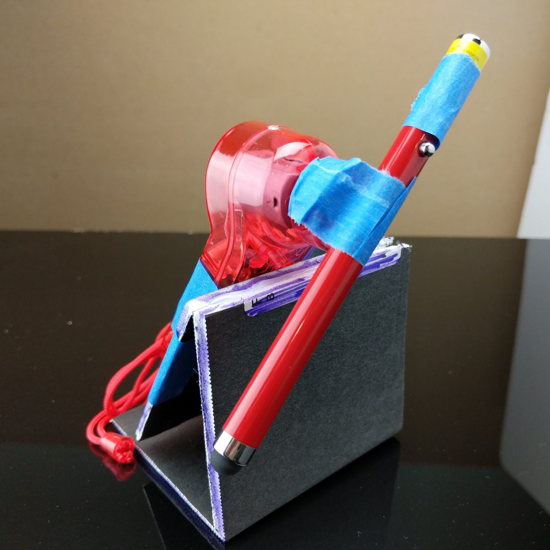
I tried a second light source. The original experiment used a laser with a beam spreader to project a horizontal plane of light across the box. I didn’t have access to a beam spreader, but I recalled another device that uses a plane of laser light: LIDAR. A LIDAR sensor uses a spinning mirror to reflect a laser beam in a circle. I could use the same principle of high-speed rotation to make a relatively continuous plane of laser light. Enter the laser fan.
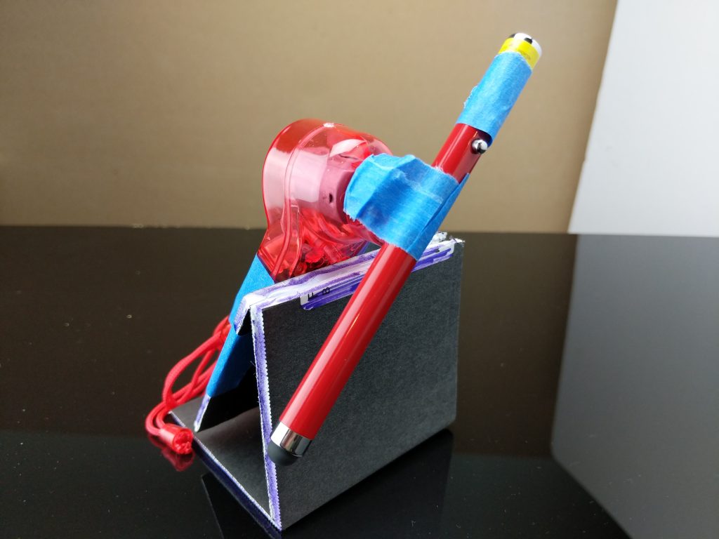
I picked a red laser pointer out as a light source. These lasers are low power and relatively safe even with direct exposure. I also picked a battery operated hand-held fan to rotate the light source. It seemed easy enough to just mount the laser on the rotating axle of the fan. With that, a bit of tape depressed the ON button to engage the laser.
Spinning laser of geometry
With the laser engaged, I needed to take care that I didn’t get a harmful exposure to my eyes. I crafted a set of laser safety glasses from a pair of clear safety glasses and six layers of blue cellophane. This attenuated the bright red laser to a faint dot when shown through the glasses. With these glasses covering my eyes, I started the laser spinning, the video recording, and produced a test spray. The following GIF shows what was captured from one of the tests.
Frame capture of laser droplet illumination
But I could get enough exhalation droplets to count. Even with a promising result with the test spray, no speaker droplets were recorded on the video. So I increased the quality of the equipment. I moved to using a 60W LED bulb in a lamp for the lighting, and a DSLR for the camera. I cut a big hole for the new camera and started testing again.
Even with the DSLR, video capture did not produce usable images. Test sprays emitted sufficient droplets, but regular speech did not. I eventually set the camera to burst mode for JPGs, at f/2.8 and 1/60th of a second. I also started blowing raspberries.
These changes made it possible to reliably capture droplets for comparison. I counted droplets from three sets of four images: a control without mask, a neck gaiter, and a two layer cotton mask. I used a blunt discernment for categorizing the droplet size. Droplets were either small and looked like dots or large and looked like strings. Droplets out of focus were ignored.
Exhaled droplets captured in beam of light
I’ve tabulated the results in a table. This makes the tabular data more rectangular. I also threw in some statistics because math makes everything more credible. Actually, the margin of error calculations reveal a lot of variability in the cotton mask test.
Image 1
Image 2
Image 3
Image 4
Averages @ 95%
Control
31L, 3S
20L, 8S
32L, 9S
28L, 4S
28L±4, 6S±3
Gaiter
17L, 7S
27L, 3S
31L, 6S
33L, 0S
27L±6, 4S±3
Cotton mask
34L, 33S
18L, 30S
4L, 25S
10L, 10S
17L±11, 25S±9
Large and small droplet counts for three masks
The results of this test are surprising. The gaiter seems to make little difference in overall spray. The cotton mask does seem effective at reducing large droplet spray, but at the cost of greatly increased small droplet spray. Small droplets are expected to float in the air longer, and therefore pose an increased risk of airborne contamination over large droplets. This differs from a finding of the original study, which showed small droplet count higher for the gaiter than any of the other masks. The cotton mask also has a much higher margin of error than the other samples. Maybe spitting in a mask doesn’t work reliably.
This was an interesting build for me. I wanted to see if I could validate a scientific paper. I wanted to see what I could learn about the masks I had. I wanted to go to the Dollar Tree, because everything’s one dollar. The process reinforced my belief in the scientific method, and the cause of science in general.
Many things can go wrong.
You need to be diligent in your testing process.
Sample sizes matter.
Keep an open mind, because your preconceived notions may be wrong.
I also found that I could not replicate the experiment using only low-cost materials. Science experiments often require precision equipment that hobbyists don’t need. Determining an analogue for a squishy human action increases consistency. This was very evident in exhalation droplet production. But I was very pleased to capture images both with a laser beam and a focused light source. Yeah science!
I wore the first cooling garment on a walk during a Fourth of July parade in a park. It was a hot day. After wearing version 1 for a few hours I learned some lessons.
Water leaks.
Vinyl tubing becomes stiff when cold.
Flexible bladders are hard to seal with glue.
Submerged pumps are harder to access.
Cold water in humid air collects moisture.
It was hard to route the hose.
I wanted to put some of the lessons into practice when designing my next cooling garment prototype. So the next version was quite different from the first.
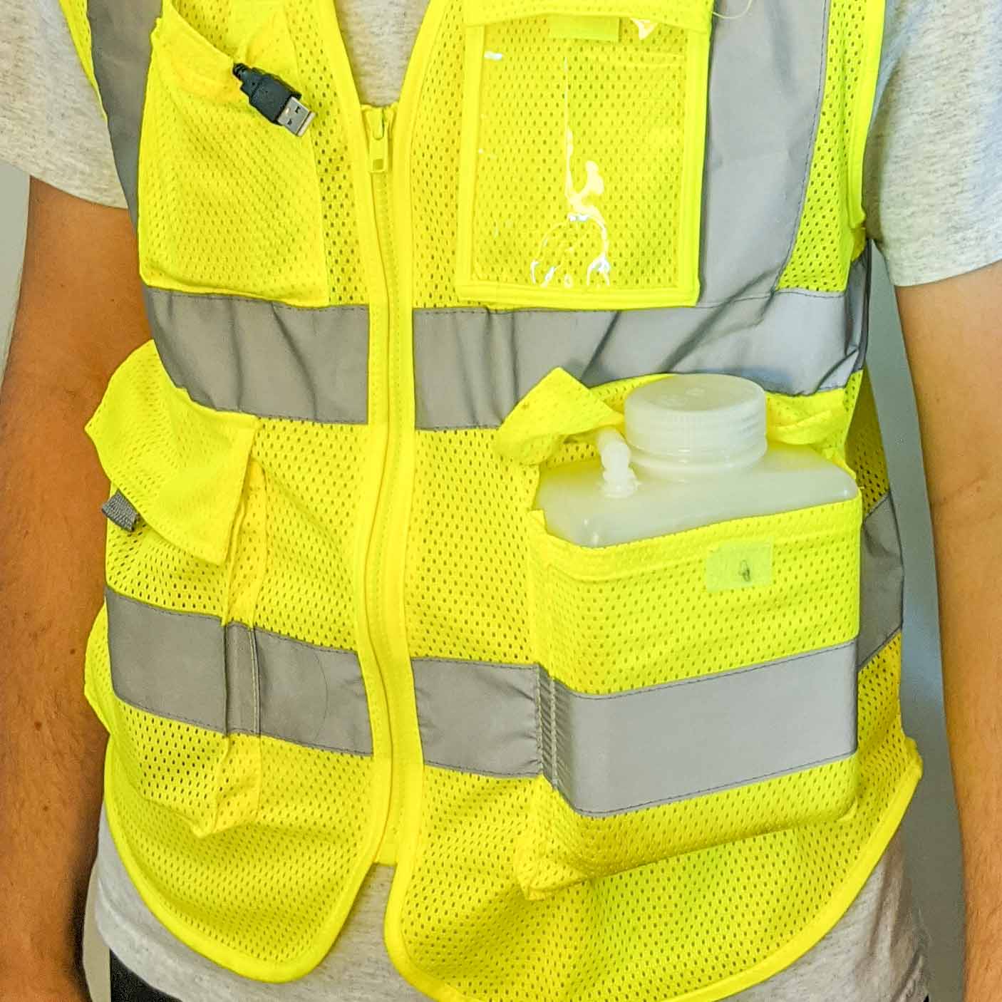
The first thing to go was the backpack. It was too difficult to route the host through cloth layers. I didn’t like picking out seams to make holes. I wanted a frame I could sew the hose on to. I went looking for a mesh vest.
The mesh vest had several advantages. First, air flows through it. This could help with cooling and evaporation. Second, the holes in the mesh would allow easy sewing. Third, a fitted vest would hold the hose close to my body. I found a thin monofilament fishing line worked well for securing the hose to the vest.
I decided a rigid vessel to hold ice and water would be easier to seal. I purchased a Nalgene bottle with a wide mouth. I also purchased 10 feet of silicone tubing and right angle couplings. I drilled holes in the top and bottom of the bottle and glued in the couplings. Water flowed out the bottom and in through the top. The wide screw top lid allowed ice to be added.
I knew I wanted the pump to be outside the bottle. This would leave more room for ice. The addition of the couplers meant that I could add and remove the hose and replace the pump too. The downside of an external pump is the need to prime the pump with liquid before running. The liquid cools and lubricates the pump. The easiest way to do this would be to mount the pump lower than the bottle.
A tube from the bottom of the bottle leads to a pocket holding the pump.
I wanted to balance the weight across both side of the vest, as much as I could. So I ran hose from the left pocket and the bottle to the right pocket and into the pump. The pump runs on 5v from a USB connection. For this application, I used a USB power bank to run the pump. I ran the cable from the bottom pocket to the top pocket where the bank fits.
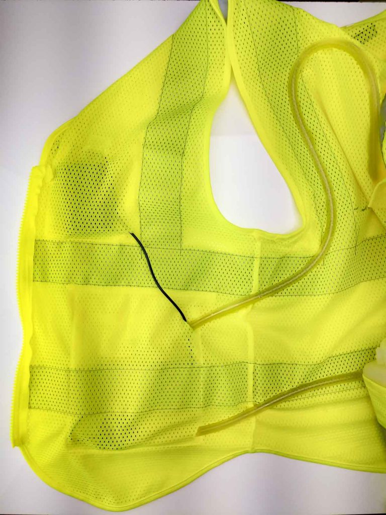
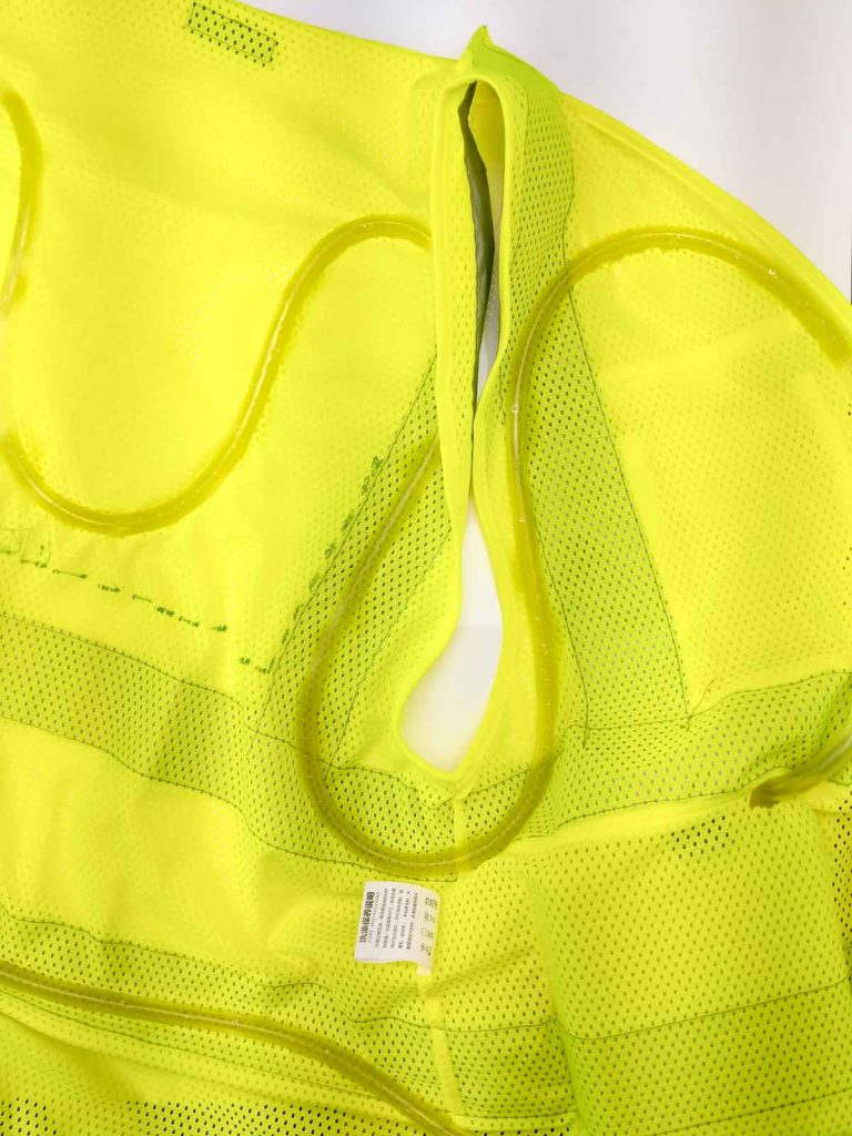
Choosing how to route the hose around the vest could have gone better. I needed a mannequin, or another large human model. I wanted the fit of the vest and the weight of the components to hold the hose against my body. I found three places that would work: pectorals, shoulder blades, and lower back. I asked my assistant to draw on the back while I wore it. I wound the 10′ of silicone hose around the back, securing it with fishing line. More hose would allow more coverage.
Serpentine tubes carrying water around
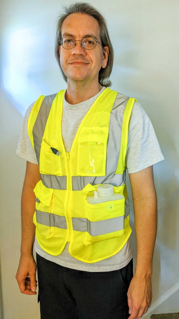
There’s not too much I can do about condensation. Move to the desert would be one solution. My t-shirt gets lines of dampness from the condensation on the cold hose. It does feel good anyway. I’m already planning version 3. It will be based on forced air ventilation. The moving air should help with evaporation and cooling.
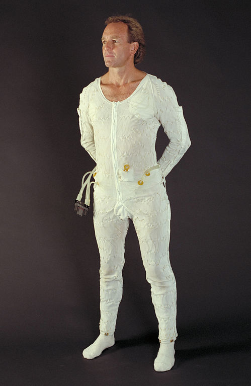
I’ve wanted to make a self regulating cooling garment for a long time. I read an article, essentially the case study from NASA, around the thermal regulation suit designed for the Apollo astronauts. Ventilation and cooling underwear, this garment contained both cooling elements and channels for increasing airflow. The cooling liquid would lower the astronaut’s temperature when needed. Initially the design called for the astronaut to manually modify the temperature regulation of the suit. The later designs allowed for an automatic temperature feedback loop to be added to the mechanism. Cooling would then automatically apply to the garment as the astronauts worked during his mission duties and exerting himself.
The original designs for NASA Liquid Cooling and Ventilation Garment LCVG utilized close fitting garment in a single coverall. A long line of tubing was sown into the garment. The material of the garment also included channels to increase airflow to the extremities. This would increase evaporation and drying in a humid and enclosed space. For my own version of a personal cooling garment, I intend to use a close fitting garment which would be worn beneath any clothing. I have procured long underwear of a spandex and silk blend, which fits close to the body. I will use this in a later iteration of the suits. I want to test out various liquid circulation patterns and heat exchangers.
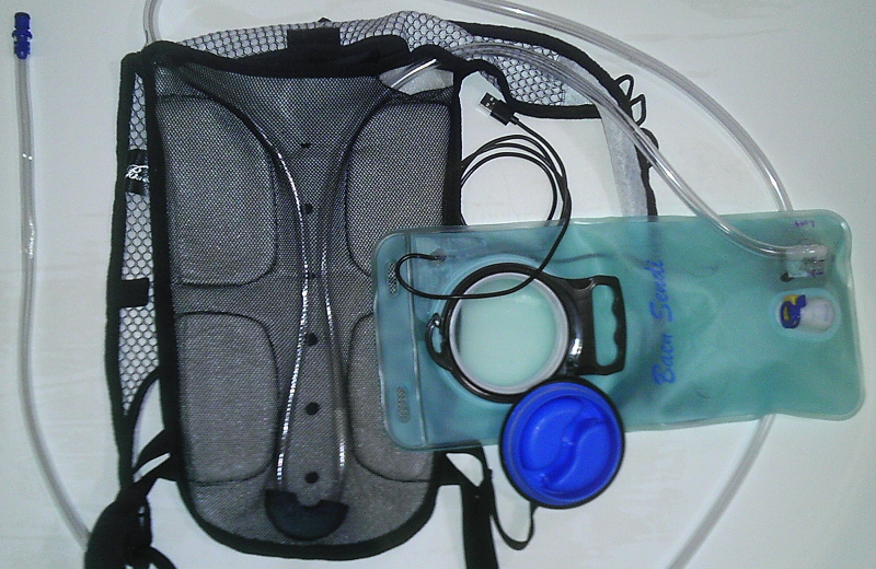
I’m starting with several different technology demonstrators to make sure that I have a reliable system for doing the cooling and ventilation. I plan on making several variations to test water cooling systems, using pumps and various means of cool in the liquid. The first design uses a typical water carrying backpack with removable bladder. Browsing Amazon, I found an inexpensive version which has a mesh fabric over the back with a padded channel for back ventilation. That space made it the perfect carrying unit for the cooling system. By cutting access holes intothe mesh fabric covering the padded back area, I was able to route a length of vinyl tube between the mesh and the padding of the backpack. The weight of the pack in this area would hold the tubing close to my body. The comfort padding on the backpack back would provide some space to prevent crushing the tubing. I procured a 10 foot length of vinyl tubing and routed the tubing through the back mesh part of the backpack. I routed the tubing into the main space of the backpack. I added two attachments on the reservoir in the back to complete the liquid circuit.
Water bladder and tubing
At this point I had roughly 5 feet of extra vinyl tubing in a loop. This tubing was handy for sticking down the front of my shirt. During the initial trial, and during the routing of the tube, I found that the vinyl tubing kinked when it bends too sharply. So I designed a minimum radius guide using Tinkercad, and printed this guide on my 3D printer. The design of the minimum radius guide was a flattened torus with a circular channel, hemispheric in nature, inset in the device. The channel was slightly larger than the diameter of the tube. When routed through the guide, the vinyl tube could not kink because the channel was too narrow.
A USB battery charger holds a large store of energy and provide a 5V output USB port. Mostly used for charging phones, the battery changer can power many other devices which run on 5 volts and use USB cables. I purchased a submersible 5 volt water pump, with integrated USB cable. This allowed me to power the pump and the entire water circulating system from a portable rechargable battery source.
The most difficult part of constructing the Cool Pac was securing the new tubing in a continuous loop to the reservoir. I was able to reuse the existing quick disconnect for one end of the tube. In order to attach the other end of the vinyl tube to the reservoir, I cut a hole in the vinyl reservoir and aligned the outlet port of pump with the hole. I then secured the top to the reservoir with CA glue and silicon sealant. The reservoir is by nature a sealed container. But in order to power the pump I needed to have the USB Power lead exit the reservoir. So I cut another role in the reservoir, and routed the USB cable out this. I secured the hole with duct tape and CA glue. I found this to be the weakest part of the circulation system.
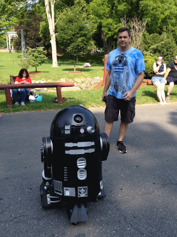
My first field tests of the Cool Pac was at a July 4th parade in Stanton, VA. The parade took place in a park. My friend and I took our Astromech droids for a roll around the park. The temperature exceeded 90°. I filled the reservoir with ice and water and started the pump. The vinyl tubing did an excellent job of transferring heat from my body to the water. One downside of having a cold liquid in the humid air of summer is condensation. Condensation did affect the clothing worn under the Cool Pac. The exit hole for the pump power line was also a weak point, a point of failure. When bending at the waist, water in the reservoir would be leak out of this hole and run down my back. Overall the system worked reasonably well. The battery supply lasted the entire 2 hours. The ice completey melted after an hour, and the water circulating was no longer cool after 90 minutes.
Datatables are very useful containers for data and have a very familiar format for database programmers. The most common method for creating them is using a DataAdapter. When using a DataAdapter, you are obliged to use the data schema of the query used to fill the datatable. Here is a method in VB.NET for creating a datatable with exactly the columns and attributes called for in your program.
Private Function CreateOrdersTable() As DataTable Dim strErrorMessage As String Dim intExitCode As Integer Try Dim OrdersTable As DataTable OrdersTable = New DataTable(“Orders”)
Dim Cost As DataColumn = New DataColumn Cost.ColumnName = “Cost” Cost.DataType = System.Type.GetType(“System.Decimal”) OrdersTable.Columns.Add(Cost)
Dim Package As DataColumn = New DataColumn Package.ColumnName = “Package” Package.DataType = System.Type.GetType(“System.String”) OrdersTable.Columns.Add(Package)
Dim CustomerID As DataColumn = New DataColumn CustomerID.ColumnName = “CustomerID” CustomerID.DataType = System.Type.GetType(“System.Int32”) OrdersTable.Columns.Add(CustomerID)
Dim AccountDate As DataColumn = New DataColumn AccountDate.ColumnName = “AccountDate” AccountDate.DataType = System.Type.GetType(“System.DateTime”) OrdersTable.Columns.Add(AccountDate)
CreateOrdersTable = OrdersTable
Catch ex As Exception strErrorMessage = ex.Message intExitCode = Err.Number() Finally If intExitCode <> 0 Then MsgBox(“Error ” & intExitCode & ” occurred. ” & strErrorMessage, MsgBoxStyle.OKOnly + MsgBoxStyle.Critical) End If End Try