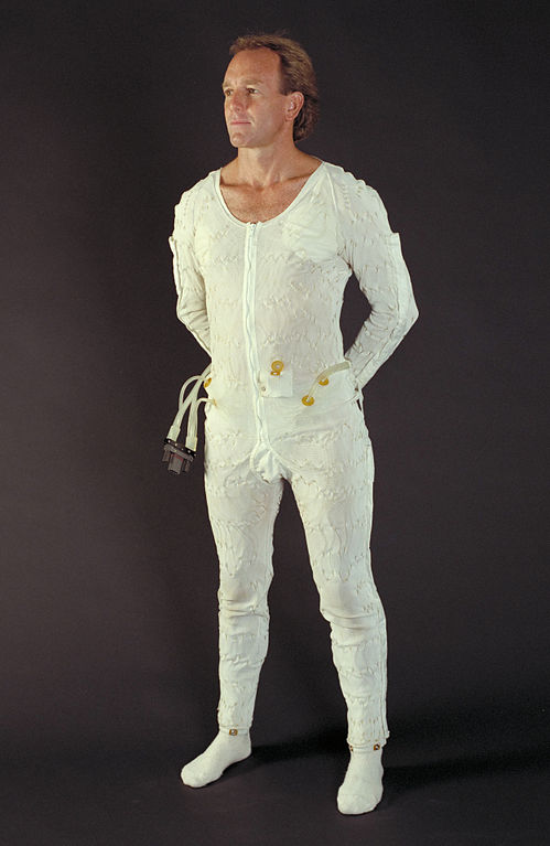
I’ve wanted to make a self regulating cooling garment for a long time. I read an article, essentially the case study from NASA, around the thermal regulation suit designed for the Apollo astronauts. Ventilation and cooling underwear, this garment contained both cooling elements and channels for increasing airflow. The cooling liquid would lower the astronaut’s temperature when needed. Initially the design called for the astronaut to manually modify the temperature regulation of the suit. The later designs allowed for an automatic temperature feedback loop to be added to the mechanism. Cooling would then automatically apply to the garment as the astronauts worked during his mission duties and exerting himself.
The original designs for NASA Liquid Cooling and Ventilation Garment LCVG utilized close fitting garment in a single coverall. A long line of tubing was sown into the garment. The material of the garment also included channels to increase airflow to the extremities. This would increase evaporation and drying in a humid and enclosed space. For my own version of a personal cooling garment, I intend to use a close fitting garment which would be worn beneath any clothing. I have procured long underwear of a spandex and silk blend, which fits close to the body. I will use this in a later iteration of the suits. I want to test out various liquid circulation patterns and heat exchangers.
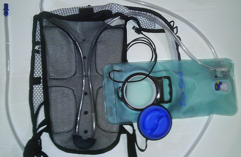
I’m starting with several different technology demonstrators to make sure that I have a reliable system for doing the cooling and ventilation. I plan on making several variations to test water cooling systems, using pumps and various means of cool in the liquid. The first design uses a typical water carrying backpack with removable bladder. Browsing Amazon, I found an inexpensive version which has a mesh fabric over the back with a padded channel for back ventilation. That space made it the perfect carrying unit for the cooling system. By cutting access holes intothe mesh fabric covering the padded back area, I was able to route a length of vinyl tube between the mesh and the padding of the backpack. The weight of the pack in this area would hold the tubing close to my body. The comfort padding on the backpack back would provide some space to prevent crushing the tubing. I procured a 10 foot length of vinyl tubing and routed the tubing through the back mesh part of the backpack. I routed the tubing into the main space of the backpack. I added two attachments on the reservoir in the back to complete the liquid circuit.
At this point I had roughly 5 feet of extra vinyl tubing in a loop. This tubing was handy for sticking down the front of my shirt. During the initial trial, and during the routing of the tube, I found that the vinyl tubing kinked when it bends too sharply. So I designed a minimum radius guide using Tinkercad, and printed this guide on my 3D printer. The design of the minimum radius guide was a flattened torus with a circular channel, hemispheric in nature, inset in the device. The channel was slightly larger than the diameter of the tube. When routed through the guide, the vinyl tube could not kink because the channel was too narrow.
A USB battery charger holds a large store of energy and provide a 5V output USB port. Mostly used for charging phones, the battery changer can power many other devices which run on 5 volts and use USB cables. I purchased a submersible 5 volt water pump, with integrated USB cable. This allowed me to power the pump and the entire water circulating system from a portable rechargable battery source.
The most difficult part of constructing the Cool Pac was securing the new tubing in a continuous loop to the reservoir. I was able to reuse the existing quick disconnect for one end of the tube. In order to attach the other end of the vinyl tube to the reservoir, I cut a hole in the vinyl reservoir and aligned the outlet port of pump with the hole. I then secured the top to the reservoir with CA glue and silicon sealant. The reservoir is by nature a sealed container. But in order to power the pump I needed to have the USB Power lead exit the reservoir. So I cut another role in the reservoir, and routed the USB cable out this. I secured the hole with duct tape and CA glue. I found this to be the weakest part of the circulation system.
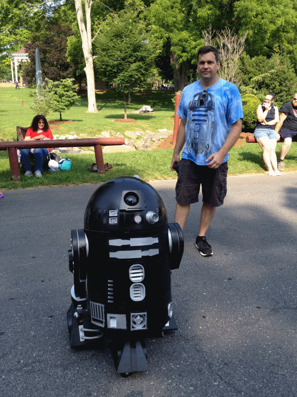
My first field tests of the Cool Pac was at a July 4th parade in Stanton, VA. The parade took place in a park. My friend and I took our Astromech droids for a roll around the park. The temperature exceeded 90°. I filled the reservoir with ice and water and started the pump. The vinyl tubing did an excellent job of transferring heat from my body to the water. One downside of having a cold liquid in the humid air of summer is condensation. Condensation did affect the clothing worn under the Cool Pac. The exit hole for the pump power line was also a weak point, a point of failure. When bending at the waist, water in the reservoir would be leak out of this hole and run down my back. Overall the system worked reasonably well. The battery supply lasted the entire 2 hours. The ice completey melted after an hour, and the water circulating was no longer cool after 90 minutes.