Omniscient Rendering

Introduction to Omniscient Rendering

Omniscient rendering represents a groundbreaking approach in the field of computer graphics and game development, positing a future where game engines can pre-calculate and understand all potential states of every object within a virtual environment. This methodology extends beyond traditional rendering techniques, which typically focus on depicting the visual state of a game at individual moments. Omniscient rendering seeks to encapsulate the entirety of an object’s possible states over time, essentially creating a “four-dimensional” model of the game world.

Interactions between user and object, and object and object, form the basis of change over time for objects, essentially creating the 4th dimension of each object. Once each 3D model are available game levels can be created. Instances of the models are created, and the relationships to all other existing objects are calculated forward in time based on possible interactions. The resulting charges are the 4D timelines of the instances of each model. The calculating algorithm forms the pre-rendering engine.

Drawing on the idea of visualizations of higher dimensions into 2D, 3D and 4D, every point in time of a 3D model can be pre-rendered and projected into a 2D visualization from every possible point of view or POV. Each visualization will be linked to all other visualizations in the POV. Every visualization, the 5D sprite, will then train an algorithm to render a 2D POV containing all sprites. The resulting “large sprite model” or “large object model” LOM will accept user input, both movement and interaction, to render the next POV or frame of display output. The LOM becomes the game engine.

Technical Foundations

4D Spatiotemporal Modeling

Omniscient rendering necessitates a robust understanding of 4D spatiotemporal modeling. In this context, the fourth dimension (time) is integrated with the traditional three spatial dimensions to create a comprehensive model that can evolve. This integration allows the rendering system to not only display the current state of objects but also predict their future states based on their historical and potential interactions within the game world. Such models are akin to a timeline for each object, detailing its past, present, and future transformations.

Temporal Coherence and Predictive Rendering

A critical aspect of omniscient rendering is maintaining temporal coherence, ensuring that object states are consistent over time. Predictive rendering techniques come into play here, where algorithms forecast the future states of objects based on predefined rules or learned behaviors. This prediction extends beyond mere animation, encompassing changes due to physical interactions, environmental factors, and player inputs, providing a seamless and dynamic gaming experience.

Computational Methods in 4D Rendering

Implementing omniscient rendering involves complex computational methods that can process and manage the 4D data efficiently. Techniques like 4D ray tracing, which extends traditional 3D ray tracing by considering time as a ray’s fourth dimension, are pivotal. This method allows for the simulation of light and shadows in a temporally consistent manner considering spatial relationships with other objects, reflecting the changing states of objects and environments over time.

Data Storage and Access

The data storage and access mechanisms for omniscient rendering are paramount, as they must handle vast datasets representing the different states of each object through time. Efficient data structures and databases are required to store these 4D datasets, enabling quick retrieval and manipulation to render the game world in real time. Techniques from big data and time-series databases can be adapted to manage this spatiotemporal data effectively.

Integration with Game Engines

Integrating omniscient rendering into existing game engines poses significant challenges, requiring fundamental changes to how game engines manage and render objects. The game engine must be capable of processing the 4D data, rendering it according to the player’s interactions and the game’s internal logic. This integration would likely necessitate the development of new engine architectures or extensive modifications to existing ones to support the complex data and computational demands of omniscient rendering.

Large Object Models

Conceptual Framework of LOMs

Large Object Models (LOMs) in the context of omniscient rendering are akin to the Large Language Models (LLMs) used in AI for natural language processing. LOMs, however, are designed to encapsulate the vast array of states and interactions possible within a 3D environment. These models are structured to comprehend and predict the behavior and evolution of objects over time, integrating vast datasets that represent the various potential states and interactions of each object in the game world.

Data Integration and Training

Integrating diverse data types and sources is crucial for training LOMs effectively. This includes spatial data, temporal sequences, interaction patterns, and physical properties of objects. The training process involves not only the assimilation of static and dynamic attributes of objects but also understanding the complex relationships and dependencies among them. Advanced machine learning techniques, such as deep learning and reinforcement learning, are employed to train these models, enabling them to predict future states and interactions based on past and present data.

Scalability and Performance

Scalability is a significant consideration in designing LOMs, as they must handle the complexity and volume of data in a game environment efficiently. This involves optimizing the models to work with high-performance computing resources, ensuring they can process and render the game world in real-time. Performance optimization also includes streamlining the data retrieval and processing mechanisms to minimize latency and maximize the responsiveness of the rendering engine. Optimization could include excluding physically impossible POVs for the final render.

Integration with Game Development Workflow

LOMs must be seamlessly integrated into the game development workflow to be practical. This integration requires tools and interfaces that allow game designers and developers to interact with the model, input new data, and tweak the system to achieve the desired outcomes. The development of such tools is crucial for enabling the creative process in game design, allowing for the iterative development and testing of game scenarios and interactions within the omniscient rendering framework.

Application in Game Development

Enhanced Realism and Interactivity

Omniscient rendering can significantly enhance the realism and interactivity of game environments. By pre-calculating the potential states of objects and their interactions, games can present a more dynamic and responsive world, or a simplified world. Physics engine complexity, and thus the number of possible object states, would have a large impact on game optimization. Players’ actions could have more nuanced and far-reaching consequences, as the game can render outcomes based on a comprehensive simulation of the game world’s physics and logic. This dynamism requires advances in machine learning computation. This depth of interaction creates a more immersive experience, as the environment reacts in complex ways to player decisions and actions.

Predictive AI and Dynamic Storytelling

In game development, AI behavior and narrative progression can be transformed by omniscient rendering. AI characters can use the pre-calculated state trajectories to make decisions that are more nuanced and contextually appropriate, leading to more lifelike and unpredictable interactions. Additionally, dynamic storytelling can evolve more organically, as the narrative can adapt to the multitude of possible player actions and environmental changes, creating a personalized and engaging story experience. This is an area where game development would impact game storage and delivery optimization.

Advanced Physics and Environment Simulation

Omniscient rendering allows for advanced physics simulations, where every object’s interactions with the environment and other objects are calculated in detail over time. This can lead to more realistic simulations of destruction, weather effects, and material transformations, enhancing the game’s visual and interactive fidelity. Environmental changes can persist or evolve logically based on the game’s internal timeline, providing a consistent and evolving world.

Optimization of Resources and Loading Times

While omniscient rendering is computationally intensive, it also offers opportunities for optimization. By pre-calculating object states, games can reduce the need for real-time calculations, potentially decreasing loading times and improving performance. Resource management can be optimized by loading only the necessary data for the current and imminent game states, reducing memory overhead and processing requirements. Streaming delivery is simplified as combining 5D sprites into a single 2D frame would be fast on modern GPUs.

Challenges in Game Design and Player Experience

The implementation of omniscient rendering also poses challenges in game design, particularly in balancing player freedom with narrative coherence and computational feasibility. Designers must consider how to maintain engaging gameplay and story progression when player actions can lead to a vast range of outcomes. Moreover, ensuring that players perceive and understand the depth and impact of their actions in such a dynamically rendered environment is crucial for maintaining a satisfying and rewarding player experience. Platform games may be a better fit than open world games. Open world games, or randomly generated spaces, would have the additional overhead of rendering the 5D objects and their 5D sprites at load time.

Challenges and Considerations

Computational Resource Demands

One of the primary challenges of omniscient rendering is the immense computational resources required. The process of pre-calculating and storing the vast array of potential object states and interactions demands significant processing power and memory. Managing these resources efficiently, while maintaining real-time performance in the game, is a complex technical challenge that necessitates advances in both hardware and software.

Data Management and Storage

The sheer volume of data involved in omniscient rendering poses significant challenges in terms of data management and storage. Efficiently organizing, accessing, and modifying this data in real-time to reflect the dynamic nature of the game world is a daunting task. This requires the development of new data structures and algorithms that can handle high-dimensional data with temporal components, ensuring quick access and updates as the game progresses.

Real-Time Rendering and Latency

Maintaining real-time rendering performance in the face of omniscient rendering’s complexity is another major challenge. The system must rapidly access and render the appropriate state of the game world with minimal latency to ensure a smooth and responsive experience for the player. This involves optimizing the rendering pipeline and possibly redefining rendering algorithms to accommodate the 4D data structures used in omniscient rendering.

Integration with Existing Game Development Pipelines

Integrating omniscient rendering into existing game development pipelines can be challenging, as it may require significant changes to established workflows and tools. Developers must adapt to new ways of designing, testing, and interacting with game content, which could involve a steep learning curve and substantial shifts in development practices.

Future Perspectives on Large Object Models

Advances in Computing Technology

The future of omniscient rendering is closely tied to advancements in computing technology, particularly in the areas of processing power, memory capacity, and data storage solutions. As hardware continues to evolve, with faster processors and more efficient memory systems, the computational barriers to omniscient rendering will diminish. This will enable more sophisticated and detailed simulations, allowing for even more complex and dynamic game worlds.

AI and Machine Learning Integration

AI and machine learning will play a pivotal role in advancing omniscient rendering. As machine learning models become more sophisticated, they will enhance the ability of game engines to predict and render complex scenarios in real-time. This could lead to more adaptive and intelligent game environments that can react in nuanced ways to player actions and environmental changes, pushing the boundaries of interactive storytelling and gameplay.

Virtual and Augmented Reality Applications

Omniscient rendering has significant implications for virtual and augmented reality (VR/AR). With its ability to pre-calculate and render complex, dynamic environments, omniscient rendering could provide the foundation for highly immersive VR and AR experiences. These experiences would be characterized by their responsiveness and realism, offering users a seamless integration of virtual and real-world elements.

The Horizon of Game Design

Looking further ahead, omniscient rendering could fundamentally transform the landscape of game design and development. Game designers will have at their disposal a powerful tool for crafting intricate, living worlds that can evolve and respond to players in unprecedented ways. This could lead to a new genre of games where the narrative and gameplay are genuinely dynamic, shaped by an intricate web of potential outcomes and player choices.

References and Articles

Foundational Theories and Concepts

To understand the theoretical underpinnings of omniscient rendering, references to seminal works in computer graphics and temporal modeling are essential. Key texts like “Computer Graphics: Principles and Practice” provide a comprehensive overview of foundational concepts in 3D rendering and modeling, which are crucial for developing the 4D approaches used in omniscient rendering.

Recent Advances in Rendering Technologies

Articles and papers from leading industry conferences such as SIGGRAPH and GDC offer insights into the latest advances in rendering technologies. These resources can provide detailed case studies and technical descriptions of cutting-edge rendering techniques, including real-time global illumination, advanced shading models, and predictive algorithms that are relevant to omniscient rendering.

Machine Learning and Predictive Modeling

The integration of machine learning in game development is a rapidly evolving field, with significant research being conducted on predictive modeling and AI-driven simulation. Journals like “Artificial Intelligence” and “IEEE Transactions on Pattern Analysis and Machine Intelligence” regularly publish articles on the development of AI models capable of complex predictive behaviors, which are central to the concept of omniscient rendering.

Ethical and Societal Considerations

As omniscient rendering involves collecting and processing large volumes of data, including potentially sensitive user data, ethical considerations are paramount. Publications in the fields of technology ethics and digital privacy can provide valuable perspectives on the responsible use of predictive technologies in gaming and interactive media.

Technical Guides and Manuals

For practical insights into implementing omniscient rendering, technical guides and manuals from game engine developers like Unity and Unreal Engine can be invaluable. These resources often include detailed documentation on the capabilities and limitations of current rendering engines, as well as guides on integrating advanced rendering and AI features into game development projects.

How to Build Your Own Portable Power Station

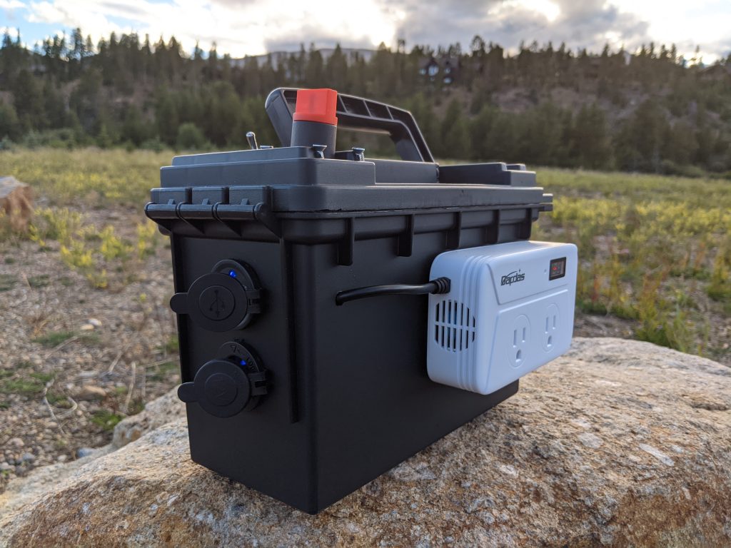
battery box sitting on a stone in a field
DIY portable power station

I love my portable power stations. I recently saw a 12V LiFePo4 battery on Amazon Vine, along with several other 12V accessories. That triggered an idea for making a brand new battery box myself. I wonder if I can make the power station out of parts I get entirely from Amazon Vine?

I’ll walk through the steps I took in making my own portable power station. Now I’ve got another option for reliable power wherever I go. You can make you own too.

What is a Portable Power Station?

A portable power station is a device that can provide electricity on the go. It is essentially a battery pack that can be charged using solar panels, wall outlets, or car chargers, and then used to power electronic devices like smartphones, laptops, cameras, and even small appliances like mini-fridges or electric grills.

The main advantage of a portable power station over traditional generators is its fuel source. It does not require any fuel or oil to operate and does not produce any harmful emissions. This makes it an ideal choice for outdoor activities like camping and hiking where you want quiet, clean power .

The most important decision when choosing a portable power station is how much power (wattage) is available. A laptop and a coffee pot take only a little power. A blanket or a kettle takes more. If you want to run a refrigerator or a space heater all day you need a much bigger system. Luckily UL listed electrical appliances list their wattage use.

Uses of a Power Station

Camping

I use my Jackery 500 every camping trip. It powers LED lights, charges my phone, my camera batteries, headlamp, and rechargeable flashlights.

On my first trip this summer, I used it to run a mini-fridge, which I got on Vine. The mini-fridge takes a lot of power; I ended up using the Jackery one day, my Bluetti EB3A the second day, and recharging both from the truck alternator. But it kept the meat and sodas cold!

battery box powering electric kettle
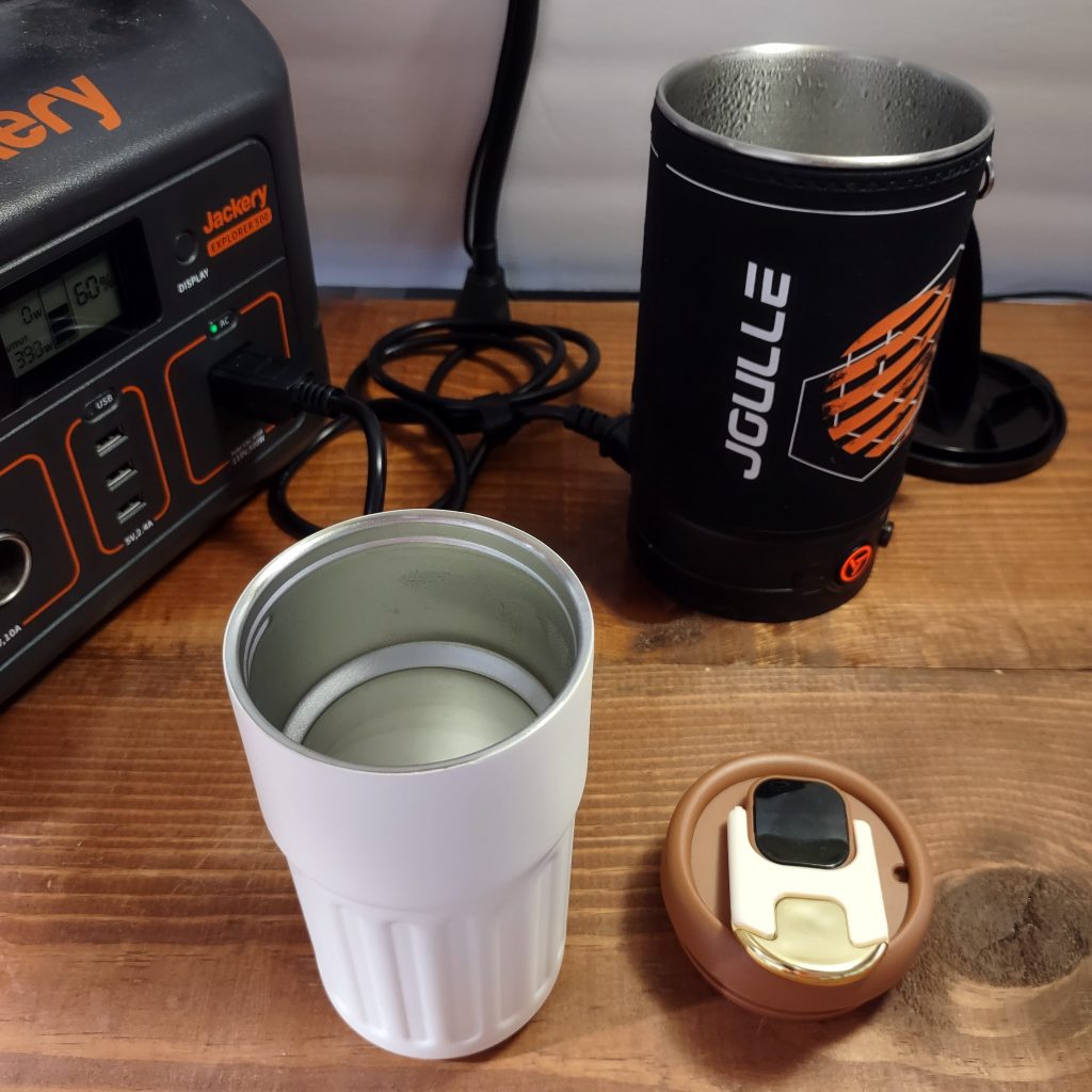
Boiling water with Joulle kettle and Jackery

Cooking at the campsite has never been easier. I have a 5 cup Mr Coffee coffee pot for coffee. It also makes good soup and heats hot dogs. I have a Joulle 500W kettle to boil water, make oatmeal, and pop corn. My favorite appliance is the Dash mini griddle. I’ve tried

  • mini quesadillas
  • ground sausage
  • hamburgers
  • pancakes
  • scrambled eggs

Having 120V electric appliances at camp means you don’t need a fire to cook.

My favorite use while camping has to be running a 12V electric blanket. I have a blanket with a 1 hour timer. I turn on the blanket, get warm and fall asleep, and the blanket shuts off automatically.

Around the house

I also take my power station all around the house and garage when I’m tinkering.

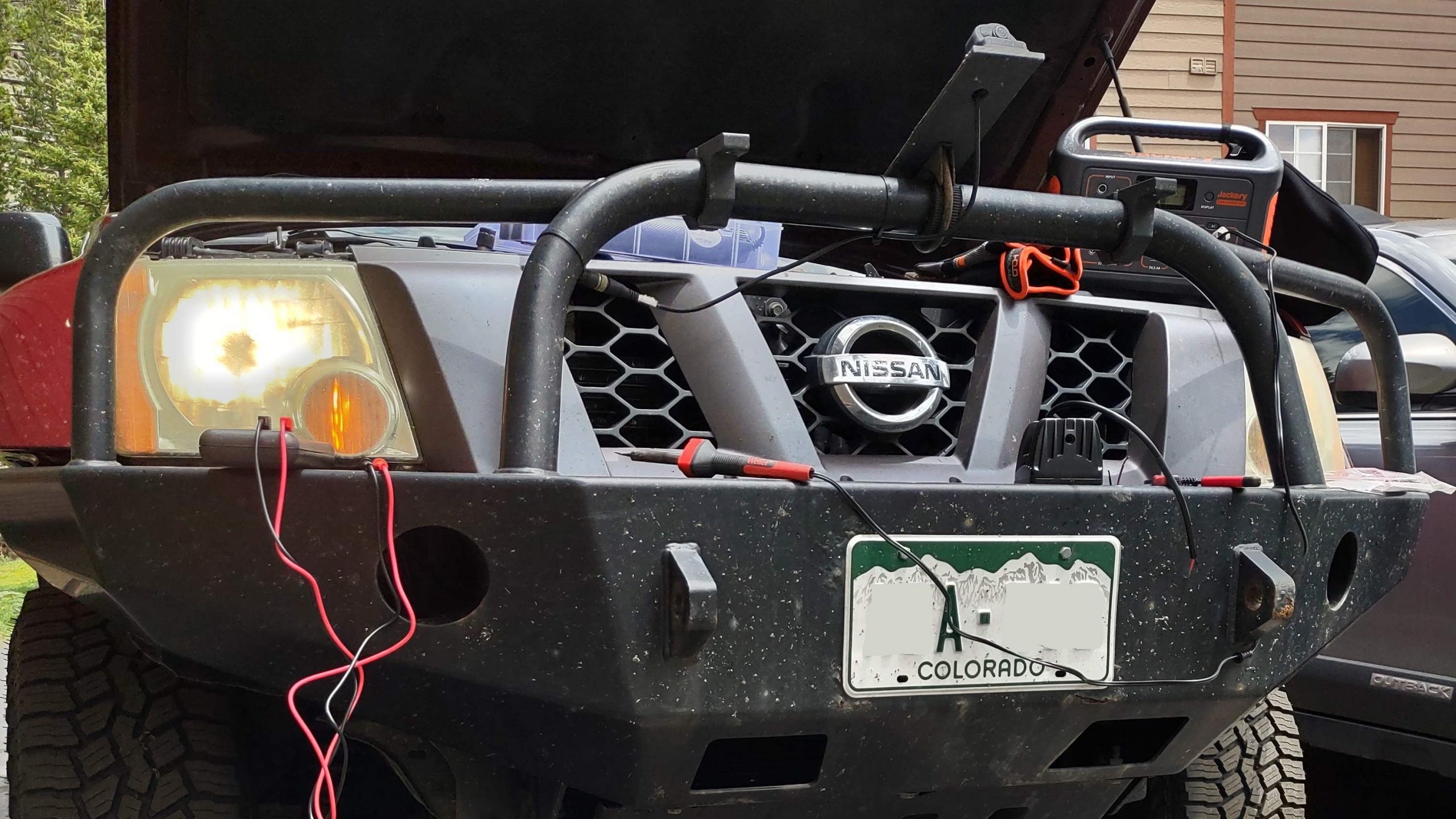
Nissan Xterra with the hood up, tools in the foreground
Jackery running a soldering iron
  • Plug in a lamp for more light
  • Vacuum the truck
  • Heat soldering iron for wiring
  • Run a pump sprayer to wash the truck
  • Trickle charge a battery

Power without an extension cord is very convenient.

Power outage

When the house power fails, having portable power stations really shines. Just like when camping, I can cook and have light and a warm blanket. More importantly, I can run my laptop all day if needed. For a remote IT worker, this is critical.

Components

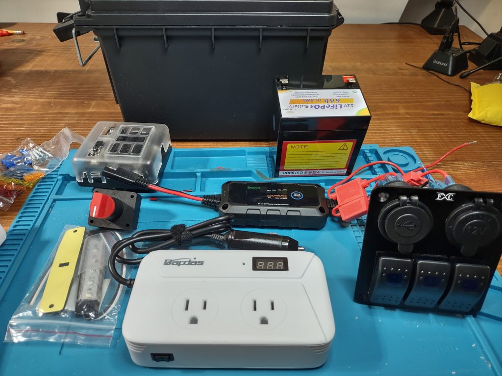
components for battery box
switch, battery, inverter

Battery

I saw the FLLEEYPOWER 12V 6Ah LiFePO4 Battery on Vine. Its small capacity meant it wasn’t going to run big loads for hours. P=IV, so 144W would use 12 amps (12A) at 12 volts (12V). This battery is only rated for continuous discharge of 6A in 1 hour, or 72W, and 144W for 3-5 seconds. The dimensions are small though. I thought it would fit in an ammo can.

12V Output DC Power

You’ve seen them. The round 12V socket, a.k.a the cigarette lighter outlet. A common 12V fitting on all cars. My truck has 4, one of them I installed myself on the rear bumper.

You can plug in many car accessories. USB chargers, portable vacuums, tire inflaters to name a few. Most any automotive parts shop will carry a panel with a pair of USB ports, a 12V socket, and a couple of switches. I got the FXC Blue 3 switch panel from Vine.

120V Output AC Power

The big deal in portable power is AC power, or line power, or 110 power. It’s the power you get in your house when plugging a TV into a wall socket. It’s provided by the local electric utility company via the electric grid. In portable off-grid systems AC power comes from inverters.

Inverters transform 12V DC current into 120V AC current. Refer the Edison vs. Tesla cage match. For AC power on the battery box, I only had a few amp-hours of capacity, so I settled on a low power inverter. The Bapdas 200W car inverter fit the bill. Plus it has a voltage display.

Fuse Block

Current flows cause heat. Heat causes fires. Circuit protection stop fires. Fuses protect 12V circuits.

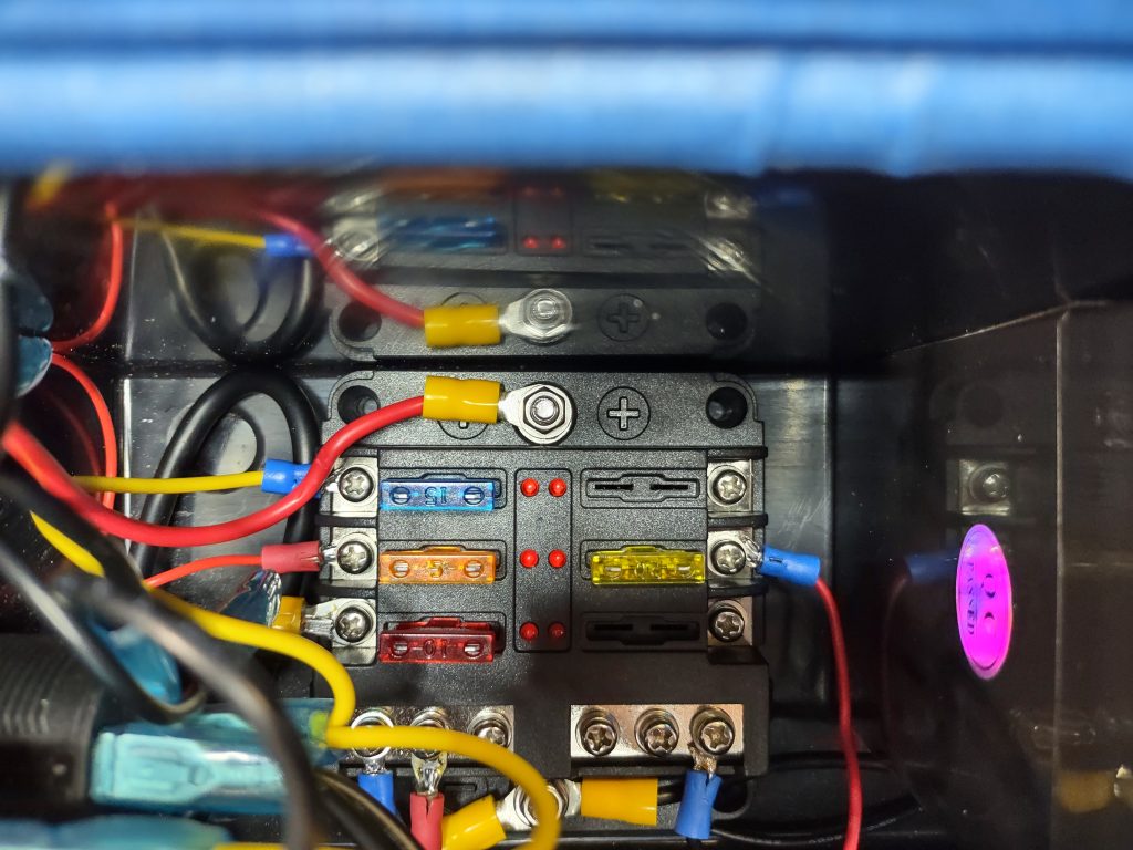
A fuse block combines separate circuits, easy fuse replacement, and common neutral bus bars. Separate circuits lets you add multiple switches and different sizes of fuse depending on load. I got a 6 fuse block from POWO Carlife.

Switch

Who doesn’t like a chunky switch? When I saw the tall 100A shutoff switch from Autoxbert I knew I was going to drill a hole and mount that switch inside the box. Most of the fancy electronic power station have a push button on/off switch.

Case

I thought an ammo box, a tackle box, or some other type of lidded box a handle would work well. Plastic would be cheaper and easier to modify. I couldn’t find what I was looking for on Vine, so I ordered the Sheffield ammo can from Amazon.

I made sure I had the measurements for the battery, fuse block, and inverter before ordering the box. Everything needed to fit inside or outside, on the sides or top. Round divots in the lid, the same side as the chunky switch, solidified the selection.

Solar panel

The ultimate off-grid power source is a solar panel. But solar panels are tricky in this case. For a 12V system, most “portable” panels are the size of 2 pizza boxes. Most of the panels showing up in Vine are 5V 3W-5W. Way too small to power even this modest system.

Charge controller

Bigger solar panels usually run at higher wattages with more variability. For example, a typical residential panel generates current from 12V on cloudy days to 18V in full sun. A charge controller regulates this voltage fluctuation and provides the correct voltage to the panel. I did find a 10A controller from Enovolt on Vine.

Light

Ever wanted a flashlight that will run for days? Every power station comes with a light. I had a 12V LED light in my electronics grab bag.

Construction

Measure once, cut twice. I think that’s how it goes.

The construction process began once all the materials had come in. First I stuck the battery, fuse block, and 12V sockets in the ammo can to make sure it all fit. I try to take into account routing and bending wires.

I broke the three switches that came with the 12V sockets at this point. The set was fully wired from the factory. But not how I wanted it wired. The wire lugs were firm. So I ordered some small but fine metal switches.

Next comes drilling holes. You don’t want to run a drill bit into the battery once it’s mounted. The cutoff switch was an 1/8″ larger than the divot. Nothing that a step drill bit and steady hand won’t handle. The light switch went in on top too.

The base plate for the 12V sockets was just wide enough to require cutting the lid bracing. Because I had already tossed the switches, I tossed the plate and mounted the sockets directly to the ammo can. I already knew how far into the can the sockets and wire projected.

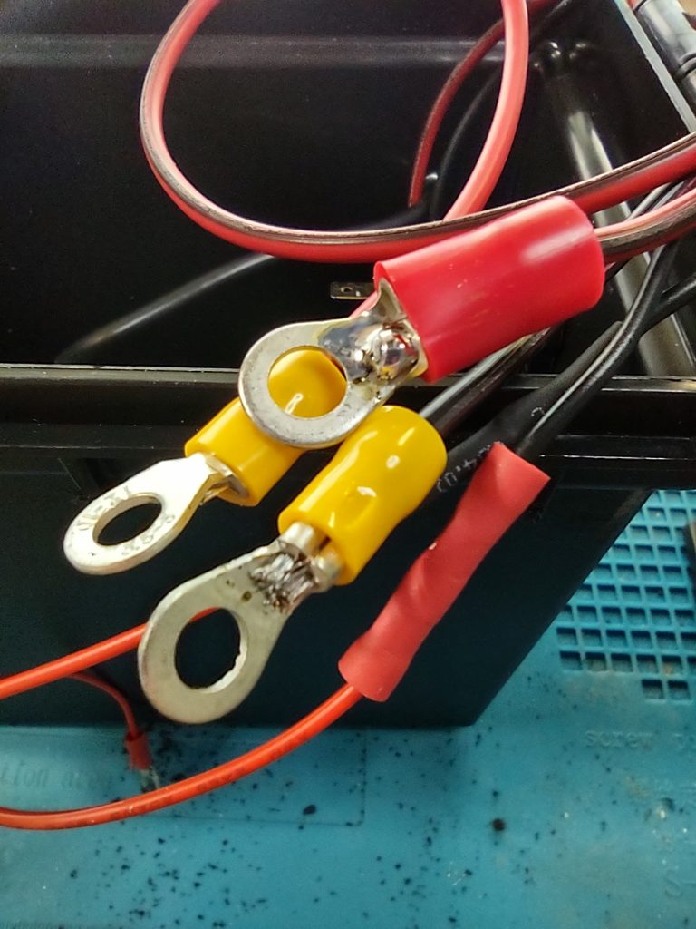
I prefer to solder and shrink wrap connections. This gives a stronger joint. But ring terminals make it easy to wire a fuse block. So I solder the wire to the ring.

wires with crimped ring terminals showing soldered connections
For crimped terminals, solder the wires for extra strength

The inverter is mounted on the outside of the can. I settled on one side instead of the top. So I removed the 12V plug and drilled a hole for its cable. I put a hole opposite this for the solar panel cable. I planned to mount the charge controller inside.

The last hole was for the LED light. I found a vertical orientation worked best because the leads were centered and lay behind the lens. And the battery was directly behind the light, I moved the light to one edge so the hole would clear the battery.

After all the holes were drilled, it was time to lay out the wiring. Wires run from the battery to switch and fuse block. Wires lead to the sockets and light and switches and inverter. Wire to crimp, wires to solder, terminals to screw down.

wires and fuses in the fuse block
The fuse block sits between the battery and 12V sockets

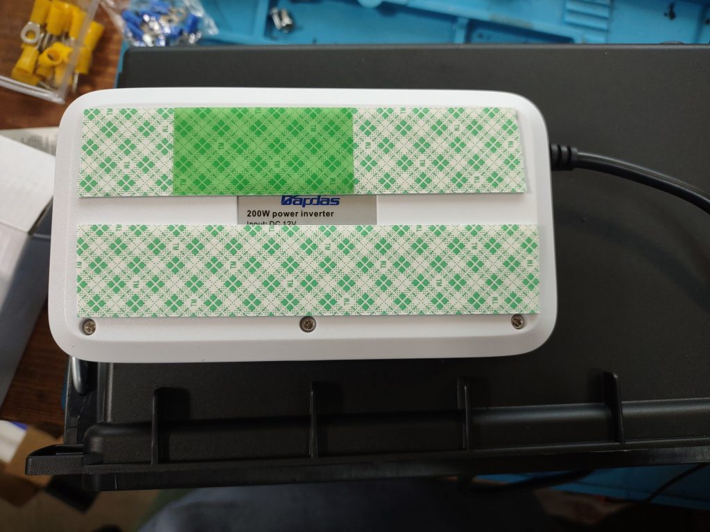
Final mounting used some bolts, some flanges and nuts, and some feet of double sides tape. Overall it feels sturdy, but I wouldn’t want to drop it.

inverter with double sided tape on back
Double sided tape on inverter

Testing

I did a test of the wiring one leg at a time. Everything worked!

The LED light is not very bright but draws very little power.

The inverter displays the battery voltage, and loads over 100W run on it for a short time.

Both 1A and 2.5A USB chargers work. I ran the mini-fridge on the 12V outlet for about 15 mins and was satisfied.

The cut off switch is sturdy with a chunky feel. It works exactly as advertised. I’d like to add a custom cover to the terminals.

Neither a 5W nor an 8W solar panel I bought from Amazon were enough to run the charge controller. I’m considering buying a much bigger panel that’s capable of making 15V+ in direct sunlight. For now I’ve got a LiFePo charger to directly charge the battery.

Cost Breakdown

  • 120V Inverter $25
  • Case $10
  • Switch $7
  • Small switches $12
  • Battery $25
  • Solar panel $18
  • Charge controller $40
  • Fuse block $11
  • 12V sockets and switches $24
  • Total $172

This project ended up costing the same as a similar power station with a bigger battery and without the solar charging. If I did it again, I’d leave off the solar and get a LiFePo charger and larger battery.

A portable power station is a convenient and reliable source of power for anyone. I made one using inexpensive parts, the most expensive being the optional solar charge controller. Whether camping, working around the house or during a power cut, a portable power station shouldn’t be out of reach.

Thanks for reading. I had a lot of fun building this battery box: 4 full evenings after work to get it ready for a Friday camping trip. If you want to build one of your own, I’ve included Amazon affiliate links to the specific products I used. If you buy one, I get a commission but it doesn’t cost you any extra.

Building the X Desk

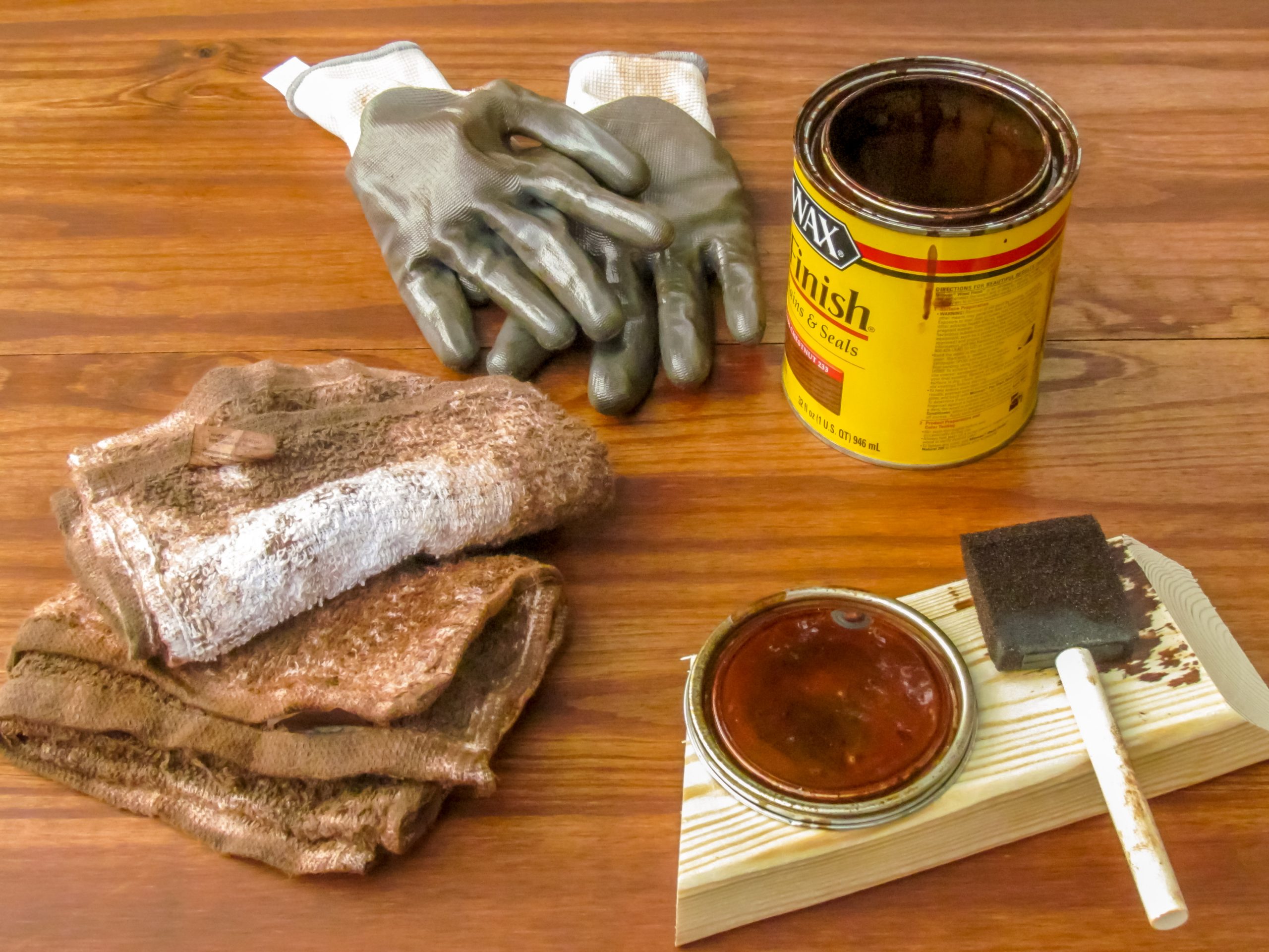
supplies for staining wood
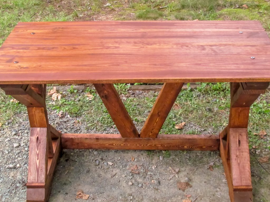
wooden desk with dark wood grain
Finished X desk

When my wife and I changed spaces in the house, I gave her my desk. That left me without a place for my computer. I decided I could make one.

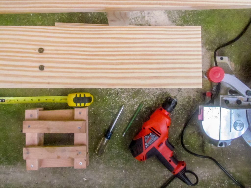
I’ve got a compound miter saw, a drill with a Kreg jig, and a tape measure. Lowes provided the lumber.

drill, saw and screwdriver

The X Desk design comes from Ana White’s website. I modified it to make the top shorter. I wanted a lighter desk that was easy to move. Except for the top, the entire desk is made from 2×4 lumber. I chose some 1×12 pine boards for the top.

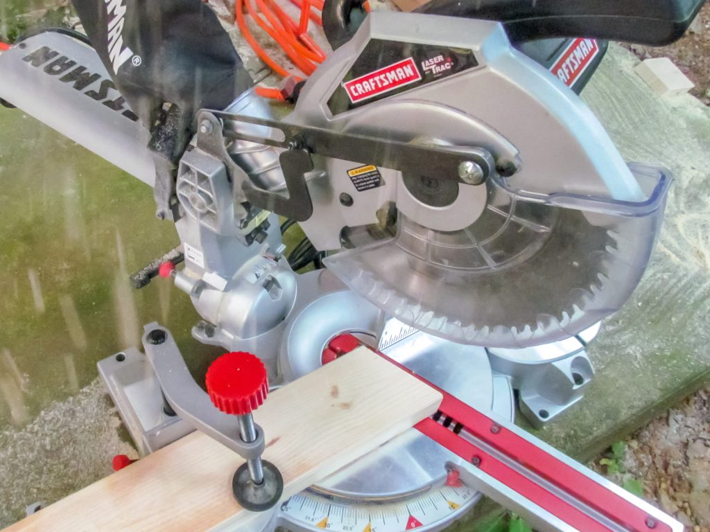
The biggest feature of the desk is the dramatic cross braces used on the single leg of the desk. Because I have a miter saw, I knew I could cut these pieces easily. I even made a modification to the design to support a narrower support. The back braces now angle 22.5 degrees.

Craftsman miter saw
I cut both 22.5 and 45 degree ends

I made a decision on the top; instead of screwing in from the bottom, or countersinking screws in the top, I would use bolts. I thought flat bronze crowns for the bolts would make nice accents. Bolts would make taking the desk apart possible too.

Clamping wood
A clamp holds the wood in place before drilling a hole

The challenge with bolts was the top layer of the legs. Two 2×4 and two more 1 inch boards meant about 4 1/2 inches to drill through and run a bolt through. I chose a trick. I embedded a T nut in the bottom side of the top leg 2×4. The nut is buried in the leg and won’t get lost. The bronze bolts run through holes in the top and holes in the leg and into the nut. Perfect.

I gave the desk a light sanding before applying stain and wax. I should have bought an electric sander and given the whole thing a finer finish. About two weeks later the wax finish has just about dried. I could clear it off and give it a good polishing. I’ve been enjoying it for more than a week now.

pieces of wood and a drill
The first set of cut pieces are ready to join

Want Better Results? Use the Right Tools

Laser spinner

Scientists are measuring the effectiveness of face mask materials. Most are using lab-quality expensive equipment designed to get absolute measurements and prove a very narrow hypothesis. But not all studies follow this pattern. A group of scientists and engineers from Duke University have released the results of their experiment using a low-cost method of analysis. They did it on the cheap.

The experiment uses common tools. The researchers used a laser, and cell phone, some custom software, and a guy wearing a face mask. The study follows standard practice for analysis and presentation, but the materials list seems one step above buying some materials at a hardware store. I found this intriguing. I’m going to recreate the experiment with stuff from the Dollar Tree.

My Build

I collected supplies from Dollar Tree. Three black foam boards, a plastic Fresnel lens, and a LED flashlight were the main items. I also got a laser pointer and a hand-held fan. To these I added a mobile phone from my current set.

I built the box based on several measurements. The first is the field of view of the camera used. I wanted the camera to capture as much of the spread of droplets as possible while minimizing extraneous elements like the walls. Spit floats a lot.

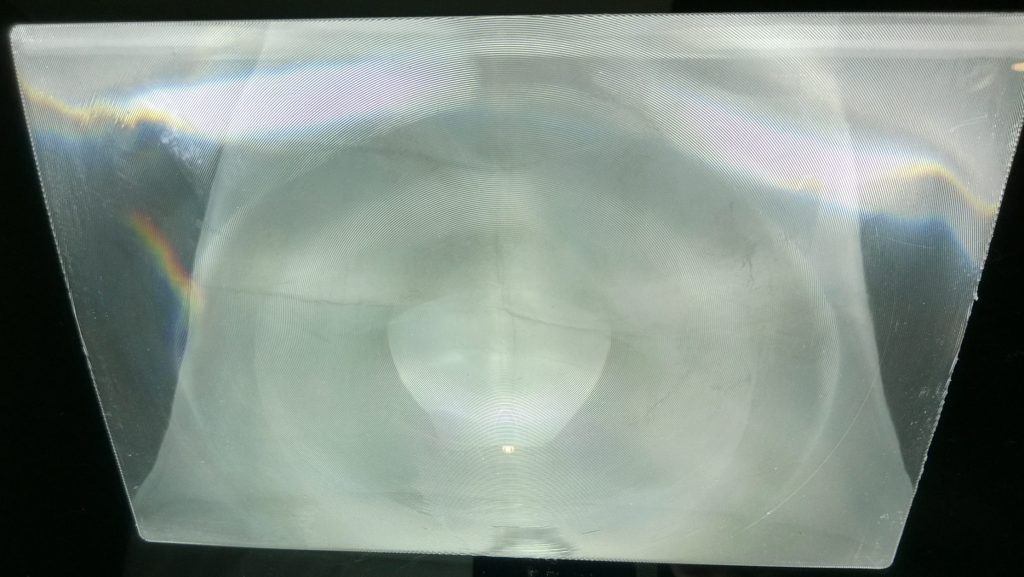
a plastic Fresnel lens
A plastic Fresnel lens

The Fresnel lens was measured next. The box needed to be wide enough to hold the entire lens, and deep enough to allow focusing of the light to occur in the center of the box. This would illuminate droplets in the narrowest horizontal and vertical slice. I wanted the spread of light from the flashlight to be the most concentrated halfway between the speaker and the camera. The Fresnel was 6.5” wide by 9.5” long and focused about 9” away. It’s strong enough to light a fire with sunlight.

The last dimension was the minimum focal distance of the camera. The box needed to be large enough that the center was within the focusing range of the camera. The minimum focal distance for the first phone I tried was 2.5”. Because the distance was so short, I felt fine making the box larger than 5” square. I didn’t need to make the box huge either.

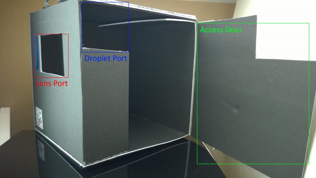
I made full use of the 20”x30” boards. The box measures 14.5” on each side. This made it easy to center the light channel, but just kept the side walls within the field of view of the camera.

black box with open panel
Labeled box for experiment

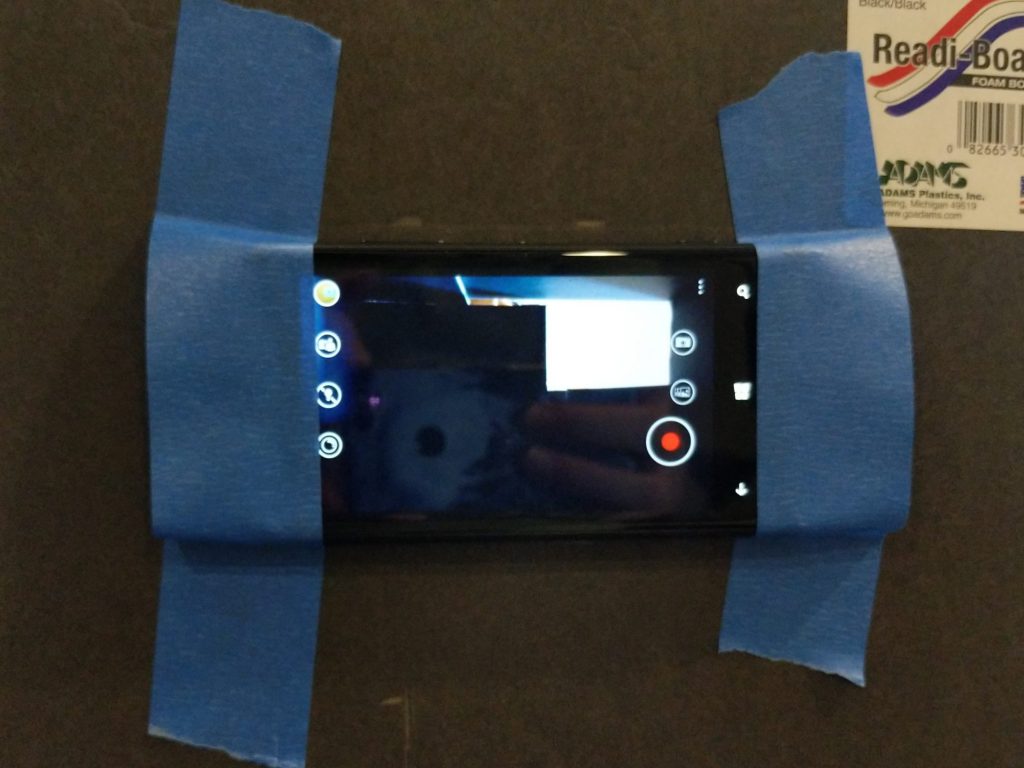
I mounted a mobile phone to the rear panel of the box. I cut a small hole and aligned the camera lens. Low tech painter’s tape sufficed to secure the phone while still allowing access to the buttons and screen. I could even see what’s in the box.

mobile phone taped down
Mobile phone affixed to box

I used water in a spray bottle to test the setup. This produced a consistent heavy spray of large and small droplets. With light passing through the lens in a beam, the droplets become visible within a horizontal bar across the middle of the box.

I tried two mobile phones to record video. Each frame can be analyzed. Video should allow identifying the start of droplet production too. Because the box has depth the droplets must travel some distance to the light beam. Using the audio track I could count the travel time in frames. The first phone, a Nokia Lumia 920, was not sensitive enough to capture droplets. The second phone, a Google Pixel 2, captured the test spray but no unmasked control droplets were visible. It’s time to try something else.

I tried a second light source. The original experiment used a laser with a beam spreader to project a horizontal plane of light across the box. I didn’t have access to a beam spreader, but I recalled another device that uses a plane of laser light: LIDAR. A LIDAR sensor uses a spinning mirror to reflect a laser beam in a circle. I could use the same principle of high-speed rotation to make a relatively continuous plane of laser light. Enter the laser fan.

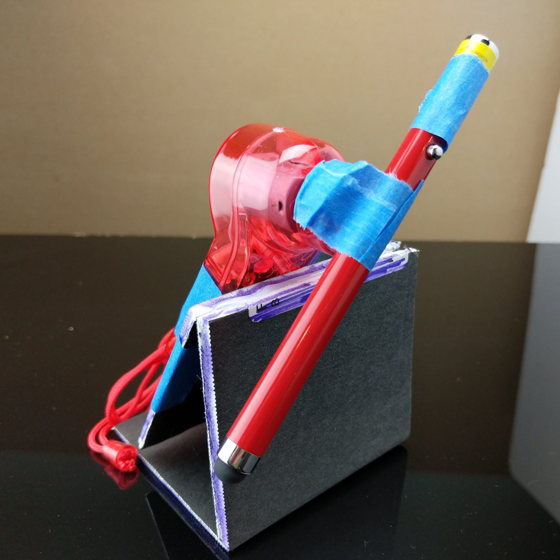
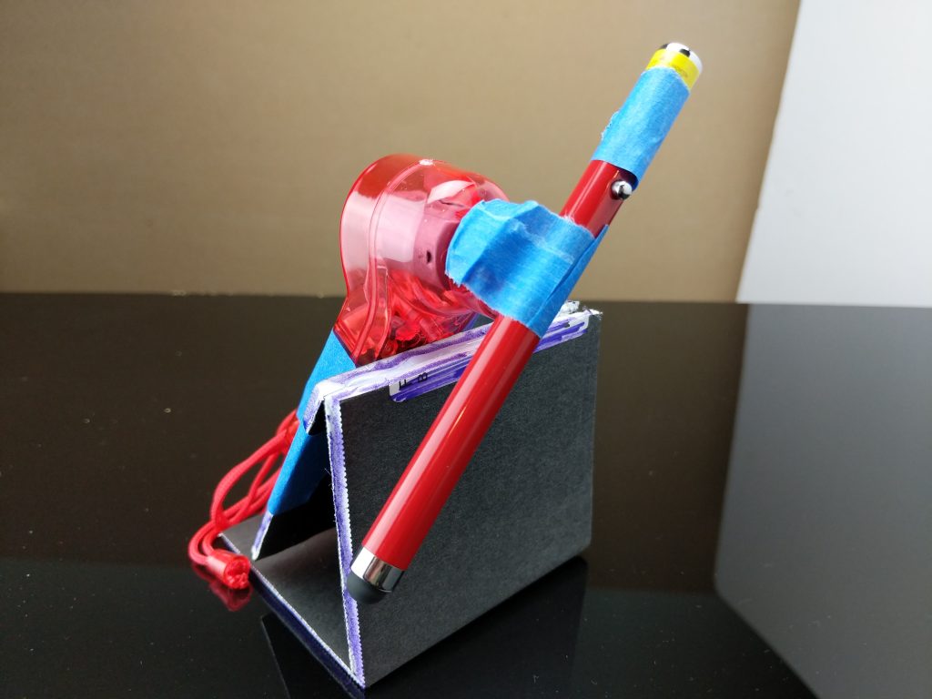
I picked a red laser pointer out as a light source. These lasers are low power and relatively safe even with direct exposure. I also picked a battery operated hand-held fan to rotate the light source. It seemed easy enough to just mount the laser on the rotating axle of the fan. With that, a bit of tape depressed the ON button to engage the laser.

a laser pointer mounted on a small fan
Spinning laser of geometry

With the laser engaged, I needed to take care that I didn’t get a harmful exposure to my eyes. I crafted a set of laser safety glasses from a pair of clear safety glasses and six layers of blue cellophane. This attenuated the bright red laser to a faint dot when shown through the glasses. With these glasses covering my eyes, I started the laser spinning, the video recording, and produced a test spray. The following GIF shows what was captured from one of the tests.

droplets illuminated by laser
Frame capture of laser droplet illumination

But I could get enough exhalation droplets to count. Even with a promising result with the test spray, no speaker droplets were recorded on the video. So I increased the quality of the equipment. I moved to using a 60W LED bulb in a lamp for the lighting, and a DSLR for the camera. I cut a big hole for the new camera and started testing again.

Even with the DSLR, video capture did not produce usable images. Test sprays emitted sufficient droplets, but regular speech did not. I eventually set the camera to burst mode for JPGs, at f/2.8 and 1/60th of a second. I also started blowing raspberries.

These changes made it possible to reliably capture droplets for comparison. I counted droplets from three sets of four images: a control without mask, a neck gaiter, and a two layer cotton mask. I used a blunt discernment for categorizing the droplet size. Droplets were either small and looked like dots or large and looked like strings. Droplets out of focus were ignored.

exhaled droplets captured in beam of light
Exhaled droplets captured in beam of light

I’ve tabulated the results in a table. This makes the tabular data more rectangular. I also threw in some statistics because math makes everything more credible. Actually, the margin of error calculations reveal a lot of variability in the cotton mask test.

Image 1Image 2Image 3Image 4Averages @ 95%
Control31L, 3S20L, 8S32L, 9S28L, 4S28L±4, 6S±3
Gaiter17L, 7S27L, 3S31L, 6S33L, 0S27L±6, 4S±3
Cotton mask34L, 33S18L, 30S4L, 25S10L, 10S17L±11, 25S±9
Large and small droplet counts for three masks

The results of this test are surprising. The gaiter seems to make little difference in overall spray. The cotton mask does seem effective at reducing large droplet spray, but at the cost of greatly increased small droplet spray. Small droplets are expected to float in the air longer, and therefore pose an increased risk of airborne contamination over large droplets. This differs from a finding of the original study, which showed small droplet count higher for the gaiter than any of the other masks. The cotton mask also has a much higher margin of error than the other samples. Maybe spitting in a mask doesn’t work reliably.

This was an interesting build for me. I wanted to see if I could validate a scientific paper. I wanted to see what I could learn about the masks I had. I wanted to go to the Dollar Tree, because everything’s one dollar. The process reinforced my belief in the scientific method, and the cause of science in general.

  • Many things can go wrong.
  • You need to be diligent in your testing process.
  • Sample sizes matter.
  • Keep an open mind, because your preconceived notions may be wrong.

I also found that I could not replicate the experiment using only low-cost materials. Science experiments often require precision equipment that hobbyists don’t need. Determining an analogue for a squishy human action increases consistency. This was very evident in exhalation droplet production. But I was very pleased to capture images both with a laser beam and a focused light source. Yeah science!

What I Learned From Documenting How to Make Coffee

brown liquid pouring on black and white ceramic mug selective color photography

I was sitting on the patio of Yoolks On Us, having just ordered breakfast. I tasted my cup of coffee and exclaimed “Hey, this is good!” I don’t have high expectations of coffee at most places, but I hold out hope.

I’ve tried coffee at gas stations. I’ve tried coffee at big coffee shops. I rarely had coffee I liked until I started making my own.

My story starts small. A friend gave me a bag of coffee to consume. They were leaving on a trip and would not be back before it lost its luster. I found an unused name-brand drip brewer in a cabinet at work. After a thorough cleaning, I made my first cup. It was okay.

I thought the problem with coffee was that I didn’t like it. Surely places that sell coffee by the cup take the time to make it properly? This is a testable hypothesis. So I decided to sample a variety of beans, made in a consistent manner, according to best practices for the drip brewer, and document my experience. This began four years ago.

Assuming the coffee brewer was working correctly, I formulated my method. 

  • Brewing: I read the manufacturer’s directions for using the brewer.
  • Precise measurements: I made a measuring cup marked for 4, 6 and 8 tablespoons so I could quickly measure the coffee grounds. I also got a graduated cylinder, a baby bottle, to measure water in 2 oz increments.
  • Quality water: I sourced water from the office water cooler. It tasted much better than the tap.
  • Testing ratios: I first tested the coffee to water ratio specified on each bag. Then I tested double and half ratios. The standard is 1 tablespoon to 4 oz. of water.
  • Timing: I set a timer of 18 minutes to get the first cup of coffee. This allowed the brew to finish while not sitting in the carafe too long.

“The difference between screwing around and science is writing it down.” 

Adam Savage

Each time I bought a new bag of coffee, I would add it to my chart. The chart included the name of the coffee, each ratio, and my judgement on taste on a scale of -2 to +2. I tried approximately 20 brands of coffee over the next year. Here’s what I concluded.

Most coffee is hot and bitter

I can’t drink hot coffee. Why would I want to burn my mouth? I always let the coffee cool. When it’s too hot I can’t taste it. Sometimes this means waiting 30 minutes or more after buying a cup.

Most coffee I’ve tried is too strong for my taste. On top of that, it’s usually too bitter. The rare exception is coffee sold as a “Breakfast Blend.” This blend is usually light or medium roasted. I assume these three observations are connected. 

I found an objective explanation while trying Maxwell House Boost coffee. I had tried light, medium, and dark roasts before. Dark roasts present the most bitter cups, but sometimes the coffee is still good. Maxwell House Boost is a medium roast which claims to have 25% more caffeine. The coffee tasted fine at all ratios, but with more bitterness than expected. I think most coffee sold by the cup is chasing more caffeine and flavor by making it strong and dark. More caffeine and darker roasts make the coffee bitter.

Coffee is different around the world

I found three distinct types of coffee beans during my testing: Columbian, Ethiopian, and Sumatran. There’s also the generic Arabica, which is just coffee grown anywhere. Most coffee I’ve tried in America that’s trying to elevate itself is labelled “100% Columbian.” The differences seem to come down to flavors that come out from the soil and the harvesting in these places.

I found Colombian coffee to have a robust and traditional coffee flavor. Ethiopian coffee has a fruity character. Sumatran coffee has some different flavors that I find off-putting. Most of my testing was done with generic Arabica coffee, and most of it was generic tasting.

Consistency matters

Because I made the same coffee over multiple days for comparison, I wanted to make consistent measurements. I learned that “heaping tablespoons” could vary greatly from one scoop to the next, so I settled on 2 tablespoon increments.

I realize now that I could have gotten a scale and done everything by weight instead of volume. This would have provided the highest level of consistency. But my test equipment worked well enough.

I found that the best ratio for brewing varied with the brand of coffee. In most cases, I found 1 tablespoon to 8 oz. of water yielded the best tasting coffee. Usually the 1 to 4 ratio would also be fine, if the coffee itself was good. Using 1 tablespoon for every 2 oz. of water would make a good tasting cup worse, and would not make a weak coffee bean taste good. If the coffee is bad nothing will save it.

I found I can drink properly prepared coffee. When the beans are good, and the roast is mild, and the strength is moderate, I enjoy the experience. I just needed to figure out what good coffee meant to me.

Cooling Garment version 2

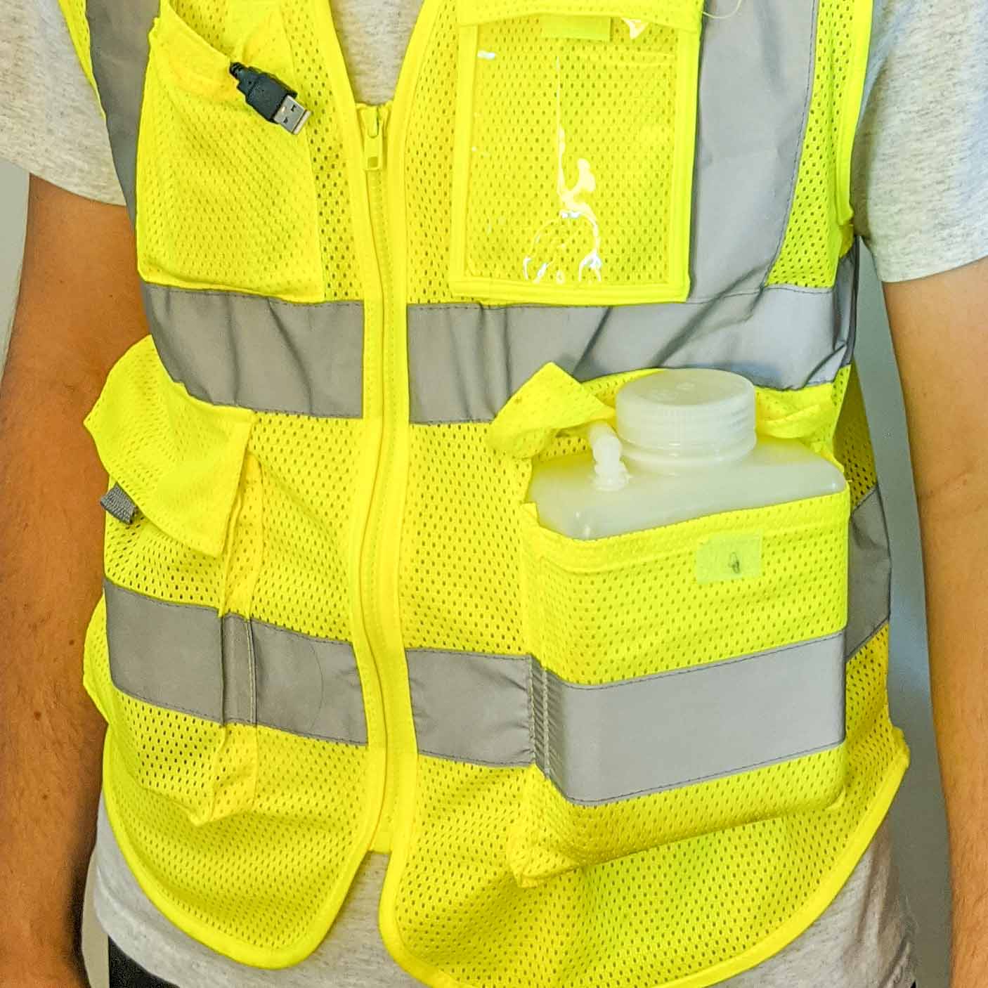
yellow safety vest with Nalgene bottle

I wore the first cooling garment on a walk during a Fourth of July parade in a park. It was a hot day. After wearing version 1 for a few hours I learned some lessons.

  • Water leaks.
  • Vinyl tubing becomes stiff when cold.
  • Flexible bladders are hard to seal with glue.
  • Submerged pumps are harder to access.
  • Cold water in humid air collects moisture.
  • It was hard to route the hose.

I wanted to put some of the lessons into practice when designing my next cooling garment prototype. So the next version was quite different from the first.

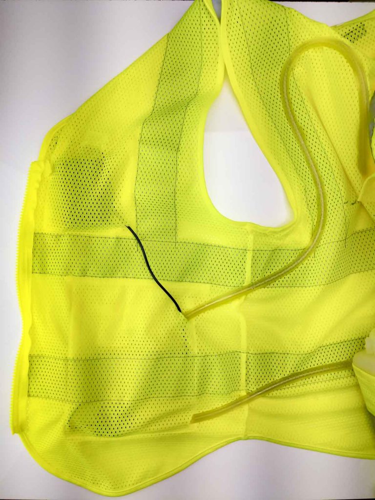
The first thing to go was the backpack. It was too difficult to route the host through cloth layers. I didn’t like picking out seams to make holes. I wanted a frame I could sew the hose on to. I went looking for a mesh vest.

The mesh vest had several advantages. First, air flows through it. This could help with cooling and evaporation. Second, the holes in the mesh would allow easy sewing. Third, a fitted vest would hold the hose close to my body. I found a thin monofilament fishing line worked well for securing the hose to the vest.

I decided a rigid vessel to hold ice and water would be easier to seal. I purchased a Nalgene bottle with a wide mouth. I also purchased 10 feet of silicone tubing and right angle couplings. I drilled holes in the top and bottom of the bottle and glued in the couplings. Water flowed out the bottom and in through the top. The wide screw top lid allowed ice to be added.

I knew I wanted the pump to be outside the bottle. This would leave more room for ice. The addition of the couplers meant that I could add and remove the hose and replace the pump too. The downside of an external pump is the need to prime the pump with liquid before running. The liquid cools and lubricates the pump. The easiest way to do this would be to mount the pump lower than the bottle.

detail of mesh vest and silicone tubing
A tube from the bottom of the bottle leads to a pocket holding the pump.

I wanted to balance the weight across both side of the vest, as much as I could. So I ran hose from the left pocket and the bottle to the right pocket and into the pump. The pump runs on 5v from a USB connection. For this application, I used a USB power bank to run the pump. I ran the cable from the bottom pocket to the top pocket where the bank fits.

Choosing how to route the hose around the vest could have gone better. I needed a mannequin, or another large human model. I wanted the fit of the vest and the weight of the components to hold the hose against my body. I found three places that would work: pectorals, shoulder blades, and lower back. I asked my assistant to draw on the back while I wore it. I wound the 10′ of silicone hose around the back, securing it with fishing line. More hose would allow more coverage.

detail of mesh vest and silicone tubing
Serpentine tubes carrying water around

There’s not too much I can do about condensation. Move to the desert would be one solution. My t-shirt gets lines of dampness from the condensation on the cold hose. It does feel good anyway. I’m already planning version 3. It will be based on forced air ventilation. The moving air should help with evaporation and cooling.

Mesh safety vest
Me wearing the cool suit

Cooling Garment version 1

I’ve wanted to make a self regulating cooling garment for a long time. I read an article, essentially the case study from NASA, around the thermal regulation suit designed for the Apollo astronauts. Ventilation and cooling underwear, this garment contained both cooling elements and channels for increasing airflow. The cooling liquid would lower the astronaut’s temperature when needed. Initially the design called for the astronaut to manually modify the temperature regulation of the suit. The later designs allowed for an automatic temperature feedback loop to be added to the mechanism. Cooling would then automatically apply to the garment as the astronauts worked during his mission duties and exerting himself.

The original designs for NASA Liquid Cooling and Ventilation Garment LCVG utilized close fitting garment in a single coverall. A long line of tubing was sown into the garment. The material of the garment also included channels to increase airflow to the extremities. This would increase evaporation and drying in a humid and enclosed space. For my own version of a personal cooling garment, I intend to use a close fitting garment which would be worn beneath any clothing. I have procured long underwear of a spandex and silk blend, which fits close to the body. I will use this in a later iteration of the suits. I want to test out various liquid circulation patterns and heat exchangers.

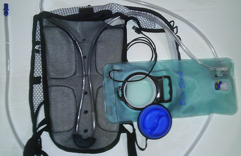
I’m starting with several different technology demonstrators to make sure that I have a reliable system for doing the cooling and ventilation. I plan on making several variations to test water cooling systems, using pumps and various means of cool in the liquid. The first design uses a typical water carrying backpack with removable bladder. Browsing Amazon, I found an inexpensive version which has a mesh fabric over the back with a padded channel for back ventilation. That space made it the perfect carrying unit for the cooling system. By cutting access holes intothe mesh fabric covering the padded back area, I was able to route a length of vinyl tube between the mesh and the padding of the backpack. The weight of the pack in this area would hold the tubing close to my body. The comfort padding on the backpack back would provide some space to prevent crushing the tubing. I procured a 10 foot length of vinyl tubing and routed the tubing through the back mesh part of the backpack. I routed the tubing into the main space of the backpack. I added two attachments on the reservoir in the back to complete the liquid circuit.

water bladder cooling unit
Water bladder and tubing

At this point I had roughly 5 feet of extra vinyl tubing in a loop. This tubing was handy for sticking down the front of my shirt. During the initial trial, and during the routing of the tube, I found that the vinyl tubing kinked when it bends too sharply. So I designed a minimum radius guide using Tinkercad, and printed this guide on my 3D printer. The design of the minimum radius guide was a flattened torus with a circular channel, hemispheric in nature, inset in the device. The channel was slightly larger than the diameter of the tube. When routed through the guide, the vinyl tube could not kink because the channel was too narrow.

A USB battery charger holds a large store of energy and provide a 5V output USB port. Mostly used for charging phones, the battery changer can power many other devices which run on 5 volts and use USB cables. I purchased a submersible 5 volt water pump, with integrated USB cable. This allowed me to power the pump and the entire water circulating system from a portable rechargable battery source.

The most difficult part of constructing the Cool Pac was securing the new tubing in a continuous loop to the reservoir. I was able to reuse the existing quick disconnect for one end of the tube. In order to attach the other end of the vinyl tube to the reservoir, I cut a hole in the vinyl reservoir and aligned the outlet port of pump with the hole. I then secured the top to the reservoir with CA glue and silicon sealant. The reservoir is by nature a sealed container. But in order to power the pump I needed to have the USB Power lead exit the reservoir. So I cut another role in the reservoir, and routed the USB cable out this. I secured the hole with duct tape and CA glue. I found this to be the weakest part of the circulation system.

My first field tests of the Cool Pac was at a July 4th parade in Stanton, VA. The parade took place in a park. My friend and I took our Astromech droids for a roll around the park. The temperature exceeded 90°. I filled the reservoir with ice and water and started the pump. The vinyl tubing did an excellent job of transferring heat from my body to the water. One downside of having a cold liquid in the humid air of summer is condensation. Condensation did affect the clothing worn under the Cool Pac. The exit hole for the pump power line was also a weak point, a point of failure. When bending at the waist, water in the reservoir would be leak out of this hole and run down my back. Overall the system worked reasonably well. The battery supply lasted the entire 2 hours. The ice completey melted after an hour, and the water circulating was no longer cool after 90 minutes.

C2-B5
C2-B5 and Andy

Using Canvas in HTML5

multi-color circles overlapping

For my Art History class on Modern Art, I created a work of Conceptual Art. This work of post-modernist theory explores a non-determinist approach to building a unique creation. The method abstracts the input of the artist, who creates a framework for the piece and then sets in motion the process which completes it. This particular work, called “Orbs”, uses the new HTML5 canvas to create a random number of randomly sized and colored circles in the webpage on each page load. Due to the large number of random elements no two views of the art work should repeat.

http://www.rnuckolls.com/concept.html
Continue reading “Using Canvas in HTML5”

Column Display of Multiple IDs in RTML

A common method for displaying a long list of products shows thumbnails arranged in rows and columns. It’s pretty easy to do if you hand code each item in each row and column. But what if you want to use a variable number of columns and products, like using the Yahoo! store Columns variable and the Specials homepage variable? This example demonstrates a Yahoo! store template which outputs the thumbnail, name and sale-price of a sequence of IDs in rows and columns using <DIV> tags. The sequence and number of columns are passed to the template. It will also check for the presence of and icon or image in the product and render a global “blank-image” image with name if there are none. Continue reading “Column Display of Multiple IDs in RTML”